


1-8
S7-200 Programmable Controller, CPU 210
C79000-G7076-C235-01
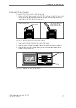
1.4
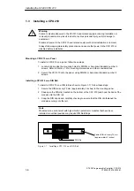
Installing the Field Wiring
Warning
Failure to disable all power to the CPU 210 and related equipment during installation or
removal procedures may result in death or serious personal injury, and/or damage to
equipment.
Disable all power to the CPU 210 and related equipment before installing or removing field
wiring.
Always follow appropriate safety precautions and ensure that power to the CPU 210 is
disabled before installing field wiring.
General Guidelines
The following items are general guidelines for designing the installation and wiring of your
S7-200 CPU 210:
S
Ensure that you follow all applicable electrical codes when wiring the CPU 210. Install
and operate all equipment according to all applicable national and local standards.
Contact your local authorities to determine which codes and standards apply to your
specific case.
S
Always use the proper wire size that will carry the required current. The CPU 210 accepts
wire sizes from 1.50 to 0.50 mm
2
(14 to 22 AWG).
S
Ensure that you do not over-tighten the connector screws. The maximum torque is
0.56 N-m (5 inches-pounds).
S
Always use the shortest wire possible (maximum 500 meters shielded, 300 meters
unshielded). Wiring should be run in pairs, with a neutral or common wire paired with a
hot or signal-carrying wire.
S
Separate AC wiring and high-energy, rapidly switched DC wiring from low-energy signal
wiring.
S
Properly identify and route the wiring to the CPU 210, using strain relief for the wiring as
required. For more information about identifying the terminals, see the data sheets in
Appendix A.
S
Install appropriate surge suppression devices for wiring that is subject to lightning surges.
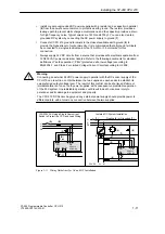
S
External power should not be applied to an output load in parallel with a DC output point.
This may cause reverse current through the output, unless a diode or other barrier is
provided in the installation.
Warning
Control devices can fail in an unsafe condition, resulting in unexpected operation of
controlled equipment.
Such unexpected action could result in death or serious personal injury, and/or equipment
damage.
Consider using an emergency stop function, electromechanical overrides, or other
redundant safeguards that are independent of the programmable controller.
Installing the S7-200 CPU 210
!
!
Содержание Simatic S7-200 CPU 210
Страница 10: ...x S7 200 Programmable Controller CPU 210 C79000 G7076 C235 01 Contents ...
Страница 68: ...3 28 S7 200 Programmable Controller CPU 210 C79000 G7076 C235 01 Getting Started with a Sample Program ...
Страница 116: ...A 16 S7 200 Programmable Controller CPU 210 C79000 G7076 C235 01 CPU 210 Data Sheets ...
Страница 126: ...F 2 S7 200 Programmable Controller CPU 210 C79000 G7076 C235 01 CPU 210 Order Numbers ...
Страница 138: ...Index 12 S7 200 Programmable Controller CPU 210 C79000 G7076 C235 01 Index ...