7-4
C7-621 / C7-621 AS-i Control Systems
C79000-G7076-C621-01
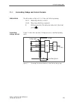
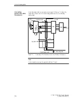
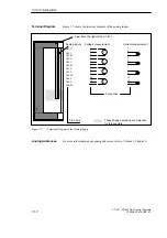
Figure 7-2 shows the connection of non-isolated sensors to a floating analog
input module.
.
.
.
Isolated
sensor
Input 24V DC
Grounding bar
ADC
Logic
AI1-U
AI1-M
C7-CPU
+
-
U
U
CM
AI2-U
AI2-M
U
+
-
L+
M
NC
NC
Analog inputs
Functional earth
M
C7-621
Equipotential
bonding cable
Figure 7-2
Connecting Non-Isolated Sensors to a Floating Analog Input
C7-621 Analog I/Os
Содержание simatic c7-621
Страница 44: ...2 26 C7 621 C7 621 AS i Control Systems C79000 G7076 C621 01 Installing and Preparing the C7 ...
Страница 64: ...3 20 C7 621 C7 621 AS i Control Systems C79000 G7076 C621 01 Configuring an MPI Network ...
Страница 74: ...5 4 C7 621 C7 621 AS i Control Systems C79000 G7076 C621 01 Attaching a C7 621 AS i ...
Страница 82: ...6 8 C7 621 C7 621 AS i Control Systems C79000 G7076 C621 01 C7 621 Digital I Os ...
Страница 100: ...7 18 C7 621 C7 621 AS i Control Systems C79000 G7076 C621 01 C7 621 Analog I Os ...
Страница 101: ...8 1 C7 621 C7 621 AS i Control Systems C79000 G7076 C621 01 Maintenance 8 ...
Страница 110: ...A 8 C7 621 C7 621 AS i Control Systems C79000 G7076 C621 01 General Technical Specifications ...
Страница 123: ...Glossary 1 C7 621 C7 621 AS i Control Systems C79000 G7076 C621 01 Glossary ...
Страница 136: ...Index 4 C7 621 C7 621 AS i Control Systems C79000 G7076 C621 01 Index ...

