7-16
C7-621 / C7-621 AS-i Control Systems
C79000-G7076-C621-01
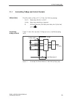
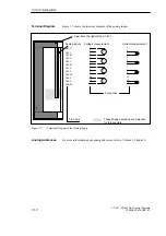
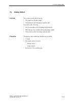
Figure 7-10 shows the terminal diagram of the analog output module.
Pin name
View from the right of the C7-621
AO-U
AO-I
AO-M
Analog output
Connection
Current output
Voltage output
15
14
16
V
A
These shaded sections are irrelevant for
this example.
Figure 7-10
Terminal Diagram of the Analog Outputs
Terminal Diagram
C7-621 Analog I/Os
Содержание simatic c7-621
Страница 44: ...2 26 C7 621 C7 621 AS i Control Systems C79000 G7076 C621 01 Installing and Preparing the C7 ...
Страница 64: ...3 20 C7 621 C7 621 AS i Control Systems C79000 G7076 C621 01 Configuring an MPI Network ...
Страница 74: ...5 4 C7 621 C7 621 AS i Control Systems C79000 G7076 C621 01 Attaching a C7 621 AS i ...
Страница 82: ...6 8 C7 621 C7 621 AS i Control Systems C79000 G7076 C621 01 C7 621 Digital I Os ...
Страница 100: ...7 18 C7 621 C7 621 AS i Control Systems C79000 G7076 C621 01 C7 621 Analog I Os ...
Страница 101: ...8 1 C7 621 C7 621 AS i Control Systems C79000 G7076 C621 01 Maintenance 8 ...
Страница 110: ...A 8 C7 621 C7 621 AS i Control Systems C79000 G7076 C621 01 General Technical Specifications ...
Страница 123: ...Glossary 1 C7 621 C7 621 AS i Control Systems C79000 G7076 C621 01 Glossary ...
Страница 136: ...Index 4 C7 621 C7 621 AS i Control Systems C79000 G7076 C621 01 Index ...

