7-2
C7-621 / C7-621 AS-i Control Systems
C79000-G7076-C621-01
7.1
Connecting Sensors to Analog Inputs
Depending on the type of measurement, you can connect various sensors to
the analog inputs:
S
Voltage sensors
S
Current sensors
This section describes how to connect sensors and points to note when
connecting them.
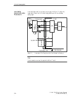
You should use shielded, twisted pair cables for analog signals. This reduces
the effects of noise. The shield of the analog cables should be grounded at
both ends. If there are potential differences between the ends of the cable, an
equipotential current can flow through the shield and cause disturbances to
the analog signals. In this case you should only ground the cable at one end.
A potential difference U
CM
(common mode voltage) may occur between the
cable AIx-M of the input channels and the reference point of the measuring
circuit M. This potential difference must, however, not exceed the permitted
limit value (see technical data). If it is possible that the permitted value for
U
CM
will be exceeded or if you cannot measure the potential difference
exactly, you must connect AIx-M with M. This also applies to unused inputs.
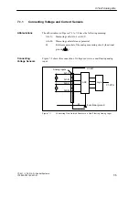
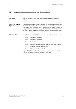
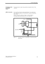
The following abbreviations are used in Figures 7-1 to 7-4:
AIx-X:
Measuring cable AIx-U or AIx-I
AIx-M:
Reference potential of the measuring cable
M:
Chassis connection of C7-621 and
Reference potential of the analog measuring circuit
(functional earth
)
U
CM
:
Potential difference between inputs and M
Isolated sensors are not connected to the local ground. They can be operated
as floating sensors. Due to the local conditions or noise, potential differences
U
CM
(static or dynamic) can occur between the measuring cables AIx-M of
the input channels and the reference point of the measuring circuit M. This
potential difference must, however, not exceed the maximum permitted
value. If it is possible that the value will exceed the maximum permitted
value for U
CM
or if you cannot measure the potential difference exactly, you
must connect AIx-M with M.
Overview
Cables for Analog
Signals
Connecting
Sensors to Analog
Inputs
Abbreviations
Isolated Sensors
C7-621 Analog I/Os
Содержание simatic c7-621
Страница 44: ...2 26 C7 621 C7 621 AS i Control Systems C79000 G7076 C621 01 Installing and Preparing the C7 ...
Страница 64: ...3 20 C7 621 C7 621 AS i Control Systems C79000 G7076 C621 01 Configuring an MPI Network ...
Страница 74: ...5 4 C7 621 C7 621 AS i Control Systems C79000 G7076 C621 01 Attaching a C7 621 AS i ...
Страница 82: ...6 8 C7 621 C7 621 AS i Control Systems C79000 G7076 C621 01 C7 621 Digital I Os ...
Страница 100: ...7 18 C7 621 C7 621 AS i Control Systems C79000 G7076 C621 01 C7 621 Analog I Os ...
Страница 101: ...8 1 C7 621 C7 621 AS i Control Systems C79000 G7076 C621 01 Maintenance 8 ...
Страница 110: ...A 8 C7 621 C7 621 AS i Control Systems C79000 G7076 C621 01 General Technical Specifications ...
Страница 123: ...Glossary 1 C7 621 C7 621 AS i Control Systems C79000 G7076 C621 01 Glossary ...
Страница 136: ...Index 4 C7 621 C7 621 AS i Control Systems C79000 G7076 C621 01 Index ...


