6-5
C7-621 / C7-621 AS-i Control Systems
C79000-G7076-C621-01
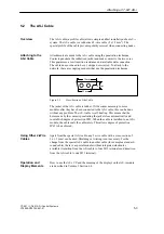
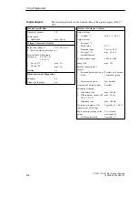
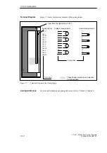
Figure 6-2 shows the terminals and block diagram of the digital outputs.
The following page has more detailed technical data about the digital
outputs.
Pin name
Shaded sections are
irrelevant for this
example.
Digital outputs
0.0
0.1
0.2
0.3
0.4
0.5
0.6
0.7
1.0
1.1
1.2
1.3
1.4
1.5
1.6
1.7
Bottom view of the C7-621
L+
M
NC
NC
Input DC 24V
Block diagram of
an output
Figure 6-2
Terminals and Block Diagram of the Digital Outputs
Terminals and
Block Diagram
C7-621 Digital I/Os
Содержание simatic c7-621
Страница 44: ...2 26 C7 621 C7 621 AS i Control Systems C79000 G7076 C621 01 Installing and Preparing the C7 ...
Страница 64: ...3 20 C7 621 C7 621 AS i Control Systems C79000 G7076 C621 01 Configuring an MPI Network ...
Страница 74: ...5 4 C7 621 C7 621 AS i Control Systems C79000 G7076 C621 01 Attaching a C7 621 AS i ...
Страница 82: ...6 8 C7 621 C7 621 AS i Control Systems C79000 G7076 C621 01 C7 621 Digital I Os ...
Страница 100: ...7 18 C7 621 C7 621 AS i Control Systems C79000 G7076 C621 01 C7 621 Analog I Os ...
Страница 101: ...8 1 C7 621 C7 621 AS i Control Systems C79000 G7076 C621 01 Maintenance 8 ...
Страница 110: ...A 8 C7 621 C7 621 AS i Control Systems C79000 G7076 C621 01 General Technical Specifications ...
Страница 123: ...Glossary 1 C7 621 C7 621 AS i Control Systems C79000 G7076 C621 01 Glossary ...
Страница 136: ...Index 4 C7 621 C7 621 AS i Control Systems C79000 G7076 C621 01 Index ...


