Siemens Energy & Automation, Inc.
Table 5
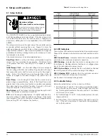
LED Fault Indications
Indication
Cause
Check/Remedy
LED 2 single flashing
Phase loss
Verify that proper three-phase incoming power is present per
paragraph 6.5, steps 3 and 4.
LED 2 double flashing
EEPROM error
Cycle power 2 or 3 times via the main breaker to reset EEPROM.
If this does not work, replace the logic board. Replacement
instructions are included with the new logic boards. Return the
faulty logic board to the factory.
LED 4 illuminated
Shorted SCR
Check SCR’s as described in paragraph 9.3.
9 Troubleshooting
9.1 Maintenance and Troubleshooting
The instructions referred to below should be carefully reviewed,
understood and followed regularly:
Step 1.
The following NEMA standards should be used as the
basis of a preventive maintenance program:
ICS 1.1-1984 (R1988) "Safety Guidelines for the
Application, Installation, and Maintenance of Solid
State Control"
ICS 1.3-1986 (R1991) "Preventive Maintenance of
Industrial Control and Systems Equipment."
Step 2. If the torque requirements for wiring connections are
not legible, refer to UL 486 "Equipment Wiring
Terminals" for nominal torque values.
Step 3. In the circumstance of a fault condition as indicated by
the opening of a short circuit protective device, refer to
Annex A ("Maintenance of Motor Controllers After a
Fault Condition") of NEMA standard ICS 2-1993
"Industrial Control and Systems,
Controllers,
Contactors, and Overload Relays Rated Not More Than
2000 Volts AC pr 750 Volts DC."
This checklist does not represent an exhaustive survey of main-
tenance steps necessary to ensure safe operation of the equip-
ment. Particular applications may require further procedures.
Should further information be desired or should particular prob-
lems arise which are not covered sufficiently for the purchaser's
purposes, the matter should be referred to the local Siemens
sales office.
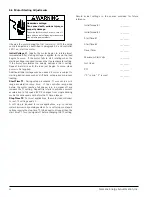
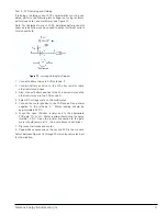
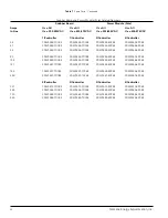
Dangerous voltages are present in the equipment which can
cause death, serious injury, or property damage. Always deen-
ergize and ground the equipment before maintenance.
Maintenance should be performed only by qualified personnel.
The use of unauthorized parts in the repair of the equipment or
tampering by unqualified personnel will result in dangerous con-
ditions which can cause death, serious injury, or equipment
damage. Follow all safety instructions contained herein.
9.2 Troubleshooting Tables
Two LED indicators on the SIKOSTART controller provide fault
indications as listed in Table 5 which includes recommended
checks and remedies. See Section 6.2 for a description of these
LED’s.
Table 6 is a general troubleshooting table listing troubles, their
possible causes, and recommended checks and remedies.
26
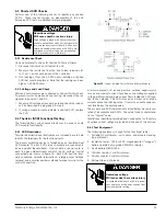
Failure to properly maintain this equip-
ment can result in death, serious injury,
property damage or product failure.
Follow the instructions listed below.


