2.4.2 Soft Start with Soft Stop
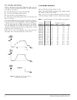
Figure 6, like Figure 5, shows the voltage and speed curves for
a soft start but with controlled deceleration. The potentiometers
have been set as follows.
U
The initial voltage is set at approximately 30%.
T1
The start time setting is greater than 0.
T2
The stop time setting is greater than 0.
T
d
The decel timer setting is greater than 0 which allows the
motor to soft stop.
The motor starting ramp is similar to the one shown in Figure 5.
But, when the run coil is de-energized, a motor stopping ramp
is formed where the motor voltage starts at 100% and decreas-
es to U2 (the initial start voltage) within the T2 time setting.
Then the voltage drops to zero after the Td time period. The time
required to decelerate may be more or less than the T1 setting
depending on the connected inertia.
When the run coil is de-energized, the speed decreases
throughout the T2 time period and then coasts to zero.
3 Controller Selection
Each controller has only one rating: “In Line”
.
Table 1 lists the SIKOSTART controller partial catalog numbers
and ratings at various rated voltages.
Table 1 is for “In Line” wiring configurations only and shows cur-
rent and horsepower ratings for units at various rated voltages.
Table 1
Controller Ratings for “In Line” Wiring Configurations
In Line
Catalog
Wiring
Horsepower at 50
v
C
Number
Amps
200V
230V
460V
575V
3RW3552...
35
10
10
20
30
3RW3554...
57
15
20
40
50
3RW3555...
69
20
25
50
60
3RW3556...
80
25
30
60
75
3RW3558...
105
30
40
75
100
3RW3565...
131
40
50
100
125
3RW3566...
195
60
75
150
175
3RW3567...
248
75
100
200
250
3RW3572...
361
125
150
300
350
3RW3583...
480
175
200
400
500
3RW3584...
720
250
300
600
700
3RW3586...
960
350
400
800
1000
Siemens Energy & Automation, Inc.
Figure 6
- Voltage, Speed, & Coil Input Curves
for Soft Start with Soft Stop.
8

