Siemens Energy & Automation, Inc.
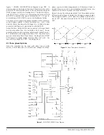
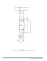
Figure 1 3RW35 SIKOSTART Block Diagram Logic PCB.
A
power supply on the logic printed circuit board accepts control
power (X1, X2) and provides power to the central processing unit
(DSP), support circuitry, and cooling fan(s). The input coil termi-
nals (A1, A2 & B1 , B2) are for commanding the motor to RUN
and STOP In addition, the input coil terminals (C1, C2) are for
commanding a KICK START to overcome breakaway friction.
The seven sets of numbered output terminals are for customer
control devices related to Motor Running (e.g.,
start / stop
devices), Motor Running at Full Voltage (e.g., to drive a bypass
contactor), and Fault (e.g., phase loss or shorted SCR).
Setup Controls. Setup controls are connected to the logic board
but are accessible from the controller’s front cover.
Seven
potentiometers provide customer adjustments: Initial Torque 1
& 2 - initial motor start voltage; start time 1 & 2 - the rate of volt-
age rise (accel ramp time); Decel timer - the length time PUMP
STOP power is applied during soft stop; Max start volts - the
max starting voltage limit; PFC - the energy saver.
2.3 Three-phase Systems
Since the controller can be used with either wye or delta
motors, a brief discussion of currents and voltages for three-
phase wye and delta arrangements with balanced loads is
included here as an aid to understanding controller setup pro-
cedures and to assist in proper controller selection.
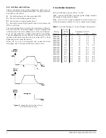
Figure 2 shows the voltage waveforms for a three-phase system
of three equal voltages separated by 120-degree phase angles.
The voltage in phase a, or Ua, leads the voltage in phase b, or
Ub, by 120
v
. Likewise, Ub leads Uc by 120
v
, and Uc leads Ua by
120
v
.
Figure 1
- SIKOSTART 3RW35 Block Diagram
Figure 2
- Basic Three-phase Waveforms
6

