4.3.2 Controller Protection
When planning your installation, be aware of potential hazards
to personnel and to the controller that can be caused by control
devices used in the system or by unique system features.
Motor Disconnect.
When any motor disconnect device con-
nected to the controller output (motor) terminals is opened dur-
ing operation, the controller continues to source full voltage if
running. If the disconnect device is reclosed, the motor will be
restarted at full voltage. When the disconnect device is opened,
a hazardous voltage is present at the controller output terminals
due to thyristor and snubber leakage.
Motor Start/Stop.
For normal operation, the controller is
designed to start and stop the motor by using signals that are
input to the controller's circuitry. Do not use the device that dis-
connects and reapplies line power to the controller for ordinary
starting and stopping of the motor.
Asymmetric Motor Windings.
Some delta motors are wound
(or re-wound) asymmetrically. This can cause low available start-
ing torque and noisy starting operation.
Power-factor-correcting (PFC) Capacitors.
Do not use PFC
capacitors at the controller output terminals. Connection to the
output terminals will damage the controller. If PFC capacitors
are used, they must be connected on the line side of the con-
troller.
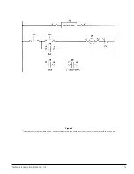
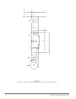
When an isolation contactor is used with the controller, the PFC
capacitors must be disconnected from the controller when the
isolation contactor is open (see figure 12).
Hazardous Environment.
Depending on the system environ-
ment, consideration must be given to unexpected hazards such
as an accidental spray of gas, liquid or solid particles or inadver-
tent contact with moving machinery.
Since the controller’s
start/stop control circuitry includes solid-state components, a
potentially hazardous environment may require the installation
of an additional hard wired emergency stop circuit that will
either disconnect AC input power to the SIKOSTART controller
or disconnect the motor from the controller.
Multiple Motors.
When the controller is used for more than
one motor, be sure the combined full load current (sum of indi-
vidual motor FLA’s ) does not exceed the controller’s rated out-
put current. Each motor requires separate overload relay pro-
tection.
Bypassing the Controller.
When the controller is mounted in
a sealed enclosure, a bypass contactor generally is used to pre-
vent heat from being generated by the thyristors during running.
If not bypassed during operation, supplemental cooling may be
required depending on operating current and enclosure size and
type.
4.3.3 Electrical Noise Suppression
Noise usually enters solid-state controls through power supply
lines, input lines and output lines. Sources of electrical noise
which can be suppressed within the power distribution system
include:
1) inductive loads, such as relays, solenoids, motors, and
motor starters operated by hard-contact devices, such as
push buttons or selector switches,
2) AC feeders,
3) high level noise generators, such as arc furnaces, high-fre-
quency welders, large AC machinery, etc.; consider electro-
statically shielded power transformers for suppression.
The most reliable way of minimizing noise coupling is to isolate
the noise generating devices and associated wiring from sensi-
tive control wiring. Group components and wires according to
signal levels and connect noise suppressors close to the noise
generators. Noise suppressors are electric components which
are used to filter, or minimize, the effect of indirect (capacitive or
inductive) coupling.
Recommended suppression practices for the noise sources list-
ed above are:
1) For an inductive load, refer to paragraph 4.4.4.
2) On AC feeders, use RF line filters.
3) On high level noise generators, use electrostatically shield-
ed power transformers.
4.4 General Wiring
Many startup difficulties are due to incorrect wiring. Observe
the following general instructions as well as the specific instruc-
tions in later paragraphs and in system instructions.
4.4.1 Power and Motor Wiring
Power supply and motor wiring ampacity should be based on
the current ratings of the motor as specified on the nameplate
and in compliance with NEC and local codes. Power and motor
supply wiring should be routed in its own separate conduit or
wireway.
Each SIKOSTART controller is available in several power supply
voltage range models. Ensure that the supply voltage and fre-
quency are within the rated range of the controller.
When welding cable is used for power wiring, a torque check
schedule should be established due to the fine strand charac-
teristic of this cable. If the ends of the cable are not properly
compressed, arcing can occur with the risk of a fire.
Siemens Energy & Automation, Inc.
Fire hazard.
Can cause death, serious injury,
or property damage.
Welding cable or other wires with fine
strands require special terminations and
may require repeated torquing of termi-
nals to prevent arcing and possible fire.
Hazardous voltage.
Will cause death or serious injury.
To avoid electrical shock or burn, do not touch
controller output terminals when power is
applied to the controller.
Hazardous voltage.
May cause property damage.
To avoid damaging solid-state power devices,
do not connect power-factor-correcting
capacitors to the load side of the controller.
10

