background image

Siemens Energy & Automation, Inc.

Table 7 

Spare Parts

Logic Board and Cooling Fan Catalog Numbers

Amps

Uc = 120V AC

In Line

Ue = All

Logic Board

1/Controller

35 - 960

91D84060005

Cooling Fan

35 - 57

0/Controller

n/a

2/Controller

69 - 105

3RW3950-8DC38

1/Controller

131 - 248

3RW3960-8DC38

2/Controller

361

3RW3960-8DC38

480 - 720

3/Controller

3RW3960-8DC38

960

3/Controller

3RW3960-8DC38

3RW3960-8DC38

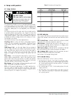
10  Spare and Optional Parts

10.1  Spare Parts

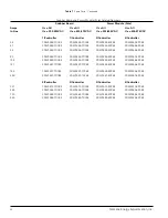
Table  7  lists  the  catalog  numbers  for the  logic  board, cooling
fan(s), snubber board(s)  and  power modules  plus  the  quantity
required for each controller.

10.1.1  Controller Amps, Uc and Ue

Three ratings identify each controller: current (Amps - In Line or
Inside Delta), control supply voltage Uc (120V AC) and main sup-
ply  voltage  Ue  (200-400V AC, 400-575V AC). Each  spare  part
relates to one or more of the ratings, e.g., each cooling fan cor-
responds to the Amps and Uc ratings regardless of the Ue rat-
ings  (Ue  =  All, where  All  means  either main  voltage  selec-
tion),whereas, each  snubber board  corresponds  to  the  Amps
and Ue ratings regardless of the Uc ratings (Uc = All, where All
means any of the three control power choices).

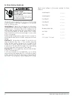
10.1.2 Fan Orientation

From one to three cooling fans are used per controller depend-
ing on the ratings. When one fan is used, it is mounted centrally
along  the  width  of  the  unit. When  two  fans  are  used, one  is
mounted to the left (L) and the other to the right (R). Left and
right are defined by facing the cover of the unit, consequently,
the  fan  on  the  left  is  the  furthest  from  the  control  terminals.
Similarly, when three fans are used, mounting locations are left
(L), center (Ctr), and right (R).

33

Содержание SIKOSTART 3RW35

Страница 1: ...S SI IK KO OS ST TA AR RT T 3 3R RW W3 35 5 I In ns st tr ru uc ct ti io on n G Gu ui id de e SFIS 4503A 0600 June 2000 ...

Страница 2: ...n used in this manual indicate the degree of hazard that may be encountered by the user These words are defined as Danger Indicates death or serious injury will result if proper precautions are not taken Warning Indicates death serious injury or property damage can result if proper precau tions are not taken Caution Indicates some injury or property damage may result if proper precautions are not ...

Страница 3: ...bleshooting 9 1 Maintenance and Troubleshooting 26 9 2 Troubleshooting Tables 26 9 3 Shorted SCR Checks 29 9 4 Thrystor SCR Testing 29 10 Spare and Optional Parts 10 1 Spare Parts 33 10 2 Optional Parts 35 3 IMPORTANT These instructions do not purport to cover all details or variations in equipment nor to provide for every possible contingency to be met in connection with installation operation or...

Страница 4: ...tor Wired with Bypass Contactor 16 11 Power Wiring for Single Speed Non Reversing Motor Wired with Bypass Contactor 17 12 SIKOSTART Controller Power and Motor Connections 18 13 SIKOSTART SIKOSTARTTerminal Connections Potentiometers and Indicators 19 14 Dimensions 25 15 Typical Isolated Power Pole and Power Module 29 16 Gate Triggering Test Diagram 30 17 Latching Holding Test Diagram 31 18 Modules ...

Страница 5: ...ive system in the following ways 1 the life of mechanical drive transmission elements is extended e g gearbox jerking is substantially reduced resulting in less wear and tear 2 reduced starting current relieves the supply network of cur rent peaks and 3 smoother acceleration of loads eliminates process or product damage 2 Operating Principle 2 1 Function Overview The SIKOSTART 3RW35 controller uti...

Страница 6: ...ontroller s front cover Seven potentiometers provide customer adjustments Initial Torque 1 2 initial motor start voltage start time 1 2 the rate of volt age rise accel ramp time Decel timer the length time PUMP STOP power is applied during soft stop Max start volts the max starting voltage limit PFC the energy saver 2 3 Three phase Systems Since the controller can be used with either wye or delta ...

Страница 7: ...ws slower and smoother acceleration of the motor and its load 2 4 1 Soft Start with Coast to Stop Figure 5 shows the relationship of voltage and speed with respect to time when a soft start is used with coast to rest The controller potentiometers have been set as follows U The initial voltage is set at approximately 30 T1 The start time setting is greater than 0 T2 The stop time is set at 0 which ...

Страница 8: ...ding on the connected inertia When the run coil is de energized the speed decreases throughout the T2 time period and then coasts to zero 3 Controller Selection Each controller has only one rating In Line Table 1 lists the SIKOSTART controller partial catalog numbers and ratings at various rated voltages Table 1 is for In Line wiring configurations only and shows cur rent and horsepower ratings fo...

Страница 9: ...losures use bypass contactors or heat exchange devices to maintain the integrity of the NEMA 12 rat ing Establish a maintenance schedule for enclosures with heat exchangers Equipment cleaning frequency should be based on the operating environment 4 3 Installation Precautions The following precautions are intended for use as guidelines for proper installation of the controller Because of the variet...

Страница 10: ...perating current and enclosure size and type 4 3 3 Electrical Noise Suppression Noise usually enters solid state controls through power supply lines input lines and output lines Sources of electrical noise which can be suppressed within the power distribution system include 1 inductive loads such as relays solenoids motors and motor starters operated by hard contact devices such as push buttons or...

Страница 11: ... watt 220 ohm resistor across each 120V AC coil An appropriately rated varistor or surge suppressor can be used in place of the R C circuit however R C circuits are rec ommended because they limit the rate of rise of noise and thus help eliminate high frequency components 4 5 Power and Motor Connections The controller input terminals L1 L2 and L3 are at the top of the unit and the output terminals...

Страница 12: ...d contactor coil and control input B1 B2 is typically run in parallel with the HIGH speed reverse contac tor coil 4 When using the controller with part winding motors these motors must be connected in their full voltage run winding configuration and the three motor leads connected to the controller output terminals 5 The motor frame should be connected to the earth ground terminal 4 6 Control Conn...

Страница 13: ...ost the circuit is broken and the controller drops out which shuts off power to the motor Bypass Contactor The applications shown in figures 10 and 11 includes a bypass contactor 2M The bypass contactor is rated to handle the running current of the motor but not the starting current The bypass contactor remains open until the controller has soft started the motor Once the motor is operating at lin...

Страница 14: ...Siemens Energy Automation Inc Figure 8 Power wiring for single speed non reversing motors in a vented enclosure circuit breaker left or fusible disconnect right 14 ...

Страница 15: ...Siemens Energy Automation Inc Figure 9 Typical power wiring for single speed non reversing motors in a vented enclosure circuit breaker or fusible disconnect 15 ...

Страница 16: ...Siemens Energy Automation Inc Figure 10 Typical power wiring for a single speed non reversing motor wired with bypass contactor 16 ...

Страница 17: ...Siemens Energy Automation Inc Figure 11 Power wiring for a single speed non reversing motor wired with bypass contactor 17 ...

Страница 18: ...Siemens Energy Automation Inc Figure 12 SIKOSTART Controller Power and Motor Connections 18 ...

Страница 19: ... 24 Contact NO Run 2 Delayed 27 28 Contact NO Fault 37 38 Contact NO Fault 35 36 Contact NC Up To Voltage 47 48 Contact NO Initial Torque 1 Initial Torque 2 Start Time 1 Start Time 2 Decel Timer Max Start Volts Not Used PFC Power On On Running Flash Phase Loss Up To Voltage Shorted SCR IMPORTANT When the DECEL TIMER is set to a value greater than zero ramp 2 settings become decel settings and run ...

Страница 20: ...the energy saving feature On lightly loaded motors the motor voltage is reduced which saves energy If the motor load increases the motor voltage is increased proportionately Note setting PFC to F disables the function Table 4 Potentiometer Setting Values Dial Initial Voltage Start Time Setting Full Voltage Seconds 0 30 0 5 1 33 1 0 2 36 2 0 3 40 4 0 4 43 6 0 5 46 8 0 6 50 10 7 53 12 8 56 15 9 60 2...

Страница 21: ...an for the motor operating under the same conditions with balanced voltages For further information refer to NEMA Standard MG 1 14 35 4 Measure individual input AC voltages L1 L2 and L3 to ground On most systems voltage will be about 57 of line voltage and nearly equal Any unbalanced voltage may indi cate an undesired ground in the motor or the SIKOSTART controller 5 Measure the control voltage It...

Страница 22: ...roller ramp ends before the motor reaches full speed turn run signal off and increase the T1 setting Repeat trial starts to achieve a smooth acceleration to full speed LED 2 changes from single blinking mode to continuously on before the T1 time elapses Stop Time T2 For most applications the motor load will coast to rest T2 setting equals 0 A soft stop is required for some applications e g to redu...

Страница 23: ...ing or Jogging Applications Controller rating to be 133 of motor rating Severe 5 times in any 60 second period Controller rating to be 200 of motor rating Very Severe 10 times in any 60 second period Controller rating to be 300 of motor rating Controller Current Ratings During Start and Run Current Cold 50v vC 115 Continuous 200 480 sec 300 120 sec 450 300 sec 500 20 sec 600 10 sec Adjustment Rang...

Страница 24: ...cycle Controller Dual Element Number Amperes Watts Amps A2 sec Fuse Rating 3RW3552 35 84 2000 15 000 60A RK1 3RW3554 57 154 2 250 18 000 100A RK1 3RW3555 69 166 4 000 80 000 100A RK1 3RW3557 80 192 4 000 80 000 100A RK1 3RW3558 105 252 7 850 257 000 150A RK1 3RW3565 131 315 7 850 257 000 200A RK1 3RW3566 195 468 7 850 234 000 300A RK1 3RW3567 248 595 11 000 416 000 400A RK1 3RW3572 361 866 15 000 ...

Страница 25: ...0 14 00 7 36 5 00 2 42 12 88 0 62 0 25 4 3 71 3RW356 131 248 11 49 15 00 7 46 9 75 0 87 13 07 1 08 0 25 4 3RW3572 361 13 56 16 4 8 83 11 25 1 16 13 21 1 77 0 25 4 3RW3584 480 720 17 42 20 35 9 10 5 25 3 0 71 17 71 1 24 0 25 8 3RW3586 960 17 62 28 32 8 68 3 99 0 91 25 71 1 13 0 25 8 5 44 5 44 Figure 14 Dimensions 3RW355 3RW3586 Upper Lower Mounting Hole Locations 25 3RW3584 Upper Lower Mounting Hol...

Страница 26: ...ondition of NEMA standard ICS 2 1993 Industrial Control and Systems Controllers Contactors and Overload Relays Rated Not MoreThan 2000 Volts AC pr 750 Volts DC This checklist does not represent an exhaustive survey of main tenance steps necessary to ensure safe operation of the equip ment Particular applications may require further procedures Should further information be desired or should particu...

Страница 27: ...power is not present check for insecure wiring connections at is not illuminated to the Run coil terminals A1 and A2 at applicable control terminals 13 14 etc and at the control devices e g start stop device isolation con tact used in the input circuit to the Run coil Bad cable connection Remove control power and check that Logic PCB to Snubber or defective printed PCB cable is secure If secure re...

Страница 28: ...otor is running while running not energized Check SCR s as described in paragraph 9 3 Motor overload relay Motor is overloaded Check for a mechanical cause of overload and clear trips during starting while running Motor not able to Check that motor comes up to speed when started by applying accelerate load across the line full voltage directly to the motor An alternative is to use the controller w...

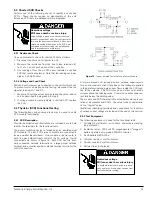
Страница 29: ...has two inter nally connected cathode terminations a large power cathode terminal and a smaller auxiliary cathode terminal or wire for the control connection A forward biased SCR anode positive cathode negative will turn on and conduct current if positive control voltage is applied to the gate terminal and gate current flows inside the SCR junc tion to the cathode The SCR turns on and stays on at ...

Страница 30: ...terminal jumper figures 18 20 to test individual SCR s for reverse blocking and forward off state voltage 2 Connect the megger across anode A and cathode K termi nals of one SCR set megger to 1 000V setting A typical reading of greater than one megohm indicates an accept able SCR and leakage current of less than one milliamp at 1 000V DC 3 Reverse the meter polarity and repeat the step 2 measure m...

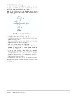
Страница 31: ...3 Also connect battery positive to the 20 ohm resistor and the other resistor end to the SCR anode A 4 Select DC voltage scale on the multimeter 5 Connect the meter positive to the SCR anode A and meter negative to the cathode K Meter reading should be approximately 9V DC 6 Touch the open 100 ohm resistor end to the appropriate SCR gate TG or LG Meter reading should drop to approx imately 1V DC Op...

Страница 32: ...Siemens Energy Automation Inc Figure 18 for 3RW355 Figure 19 for 3RW356 Figure 20 Typical configurations 32 ...

Страница 33: ...tage Uc 120V AC and main sup ply voltage Ue 200 400V AC 400 575V AC Each spare part relates to one or more of the ratings e g each cooling fan cor responds to the Amps and Uc ratings regardless of the Ue rat ings Ue All where All means either main voltage selec tion whereas each snubber board corresponds to the Amps and Ue ratings regardless of the Uc ratings Uc All where All means any of the thre...

Страница 34: ...RW3958 7DC85 3RW3955 5DC84 3RW3956 5DC85 80 3RW3958 7DC84 3RW3958 7DC85 3RW3956 5DC84 3RW3957 5DC85 105 3RW3958 7DC84 3RW3958 7DC85 3RW3958 5DC84 3RW3958 5DC85 131 3RW3967 7DC84 3RW3967 7DC85 3RW3965 5DC84 3RW3965 5DC85 195 3RW3967 7DC84 3RW3967 7DC85 3RW3966 5DC84 3RW3966 5DC85 248 3RW3967 7DC84 3RW3967 7DC85 3RW3967 5DC84 3RW3967 5DC85 3 Controller 3 Controller 3 Controller 3 Controller 361 3RW3...

Страница 35: ...ug to the controller ter minal The Wire Size Range column lists the wire sizes that the lug can accommodate Table 2 in this manual indicates the torque required for the set screw that secures the wire in the lug Complete installation instructions are furnished with each lug kit Note Mount lug under terminal as shown Table 8 Lug Kits Wye Lug Operational Lug Kit Hardware Current Part Torque Wire Siz...

Страница 36: ...hout prior notice Printed in the U S A Siemens Energy Automation Inc 1000 McKee Street Batavia IL 60510 Tel 630 879 6000 Tel 800 323 5450 http www siemens com controlsusa 2000 Siemens Energy Automation Inc Siemens is a registered trademark of Siemens AG ...

Отзывы: