Siemens Energy & Automation, Inc.
10.2 Optional Parts
10.2.1 Lug Kits
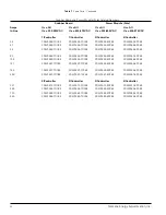
Table 7 lists lug kits for use with the SIKOSTART 3RW35 con-
trollers. Each kit provides a method of adapting a controller for
use with aluminum or copper power wiring. One kit contains
lugs for either the line or load side of the controller. Two kits are
required to add lugs to both line and load terminals.
Figure 21 shows a lug in position for mounting to the terminal.
The table 7 Lug Hardware Torque column indicates the torque
required for the screw that secures the lug to the controller ter-
minal. The Wire Size Range column lists the wire sizes that the
lug can accommodate. Table 2 in this manual indicates the
torque required for the set screw that secures the wire in the
lug.
Complete installation instructions are furnished with each lug
kit.
Note:
Mount lug under terminal as shown.
Table 8
Lug Kits
Wye
Lug
Operational
Lug Kit
Hardware
Current
Part
Torque
Wire Size
Rating
Number
(lb-in.)
Range
35, 57, 69,
2/0 to #
80 & 105
91D81755011
75
14 AWG
131 & 195
91D81755012
275
350 MCM
to #6 AWG
248
91D81755013
275
(1) 600 MCM
to #6 AWG
or (2) 250 MCM
to #1/0
361
91D81755016
275
(2) 350 MCM
to #4 AWG
480 - 720
91D81755014
275
(3) 350 MCM
to #6 AWG
960
91D81755015
275
(4) 350 MCM
to #6 AWG
Figure 21
- Mounting Lug on Terminal Point
35


