


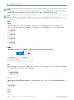
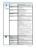


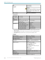


Description
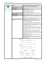
Invert the input signal with a logical NOT.
Number of inputs
1
Input data type
1-bit (future extension: or n-bit)
Input description
levelA: first input value
Number of outputs
1
Output data type
Identical to input data type
Output description
level:
the input signal will be inverted with a logical not. Exam‐
ple: a high signal gets converted into a low signal.
Settings
No settings available
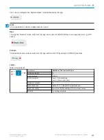
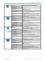
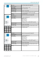
AND
Table 29: Thruth table
Input
A
Input
B
Out‐
put
1
1
1
1
0
0
0
1
0
0
0
0
Description
Combine the input signals with a logical AND.
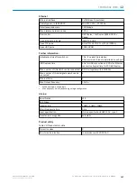
Number of inputs
4
Input data type
1-bit (future extension: n-bit)
Input description
levelA:
first input
levelB:
second input
levelC:
third input
levelD:
fourth input
Maximum 4 inputs can be linked together. If you want to link
more signals, you can work with several AND blocks.
Number of outputs
1
Output data type
Identical to input data type
Output description
level:
the output depends on the various inputs. For more
information see truth table
Settings
No settings available
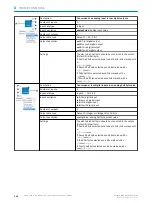
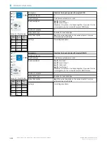
OR
Table 30: Thruth table
Input
A
Input
B
Out‐
put
1
1
1
1
0
1
0
1
1
0
0
0
Description
Combine the input signals with a logical OR.
Number of inputs
4
Input data type
1-bit (future extension: n-bit)
Input description
levelA:
first input
levelB:
second input
levelC:
third input
levelD:
fourth input
Maximum 4 inputs can be linked together. If you want to link
more signals, you can work with several OR blocks.
Number of outputs
1
Output data type
Identical to input data type
Output description
level:
the output depends on the various inputs. For more
information see truth table
Settings
No settings available
DEVICE FUNCTIONS
8
8017853.1D0S/2021-11-04 | SICK
O P E R A T I N G I N S T R U C T I O N | Sensor Integration Gateway - SIG200
119
Subject to change without notice


