


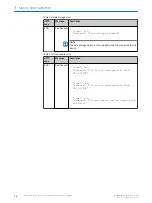
NOTE
If a logic block has been selected incorrectly, or needs to be removed, click on it
and drag it back up to the selection bar. A garbage bin will appear to remove the
selected logic gate from the workspace.
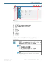
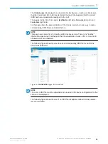
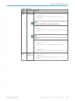
2.
Making connections from the inputs to the logic gates: Click on the desired input,
click again and mark the arrow. A connecting line is then created. Note that you
can drag the line to a desired logic gate input.
As you approach, the logic gate inputs expand to accommodate the connection
cable. As soon as the connection is made, the bends (if there are bends along the
connection), the position of the logic gate and the window size can be adjusted.
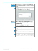
The connection is scaled automatically. An incorrect connection can be deleted by
clicking and holding the connecting line. A wastebasket icon is displayed at the top
center of the user interface.
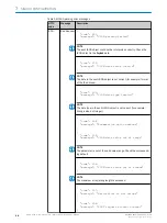
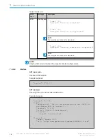
Some logic blocks require at least two input signals.
Note that the inputs must always be assigned from top to bottom (e.g. for two
inputs A+B and not A+D).
The inputs are outlined in red when connections are made to indicate that a
connection is still required in this area. The two inputs C and D are only active in
the logical truth table if a connection has been made.
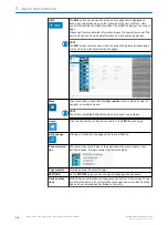
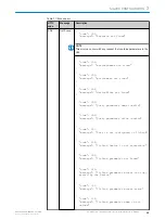
NOTE
Green input arrows and green text: a connection is possible
If a connection is not possible, the text will have red color and it is not possible to
drag a connection to the input.
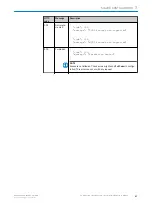
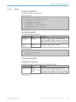
NOTE
Some inputs and logic gates have a small gear indicating that some additional set‐
tings are possible. Clicking on the gear will open the additional settings dialogue
box and allow for additional configuration (e. g. delay time).
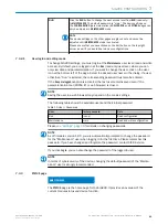
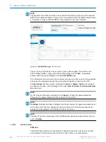
3.
Clomplete the setup by using the Transfer and Execute Flow button: the new logic
configuration is transfered to the connected SIG200.
NOTE
An error will appear if there are any improper or missing connections. The notifica‐
tion area will indicate a successful transfer.
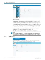
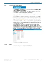
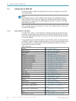
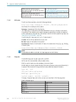
7.3.7
Settings
The following settings are possible:
Setting
Possible values
Language
english / german
7
SIG200 CONFIGURATION
58
O P E R A T I N G I N S T R U C T I O N | Sensor Integration Gateway - SIG200
8017853.1D0S/2021-11-04 | SICK
Subject to change without notice


