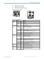
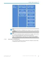
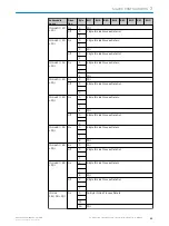

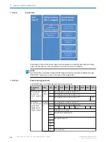
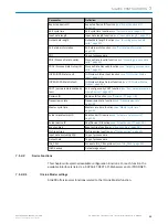
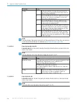

Slot
Subslot Name
Function
1
1
Configuration Module
Global configuration for SIG200
2
SIG200 Logic Editor
Logic Editor: User-defined data processing
2
1
SIG200 IO-Link Mas‐
ter
IO-Link Master functions concerning all ports (e. g.:
state of pin 2).
2…5
Various
IO-Link Device data representation used for config‐
uring IO-Link Device; must not be placed for ports
owned by REST or Logic Editor
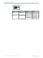
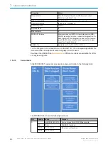
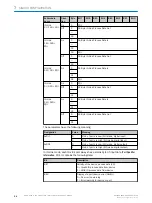
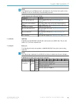
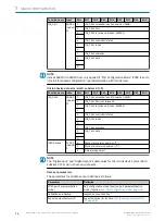
7.1.2.1.1
Process data overview (cyclic data)
The SIG200 uses incoming process data (
Process Data In
; data from the IO-Link master
to the PLC) and outgoing process data (
Process Data
Out; data from the PLC to the IO-Link
master).
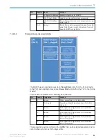
Process data is available at the following slots/subslots:
Slot
Subslot Designation
Function
1
2
Various
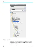
Data representation in the logic editor
2
1
Pin 2 inputs
Acquisition of digital input data at pin 2 of all IO-
Link ports
2
Various
Pin 4 digital input, digital output or IO-Link data
from IO-Link port S1
3
Various
Pin 4 digital input, digital output or IO-Link data
from IO-Link port S2
4
Various
Pin 4 digital input, digital output or IO-Link data
from IO-Link port S3
5
Various
Pin 4 digital input, digital output or IO-Link data
from IO-Link port S4
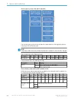
The process data options defined in the GSDML file can be selected separately, one for
each IO-Link port and one for the logic editor.
SIG200 CONFIGURATION
7
8017853.1D0S/2021-11-04 | SICK
O P E R A T I N G I N S T R U C T I O N | Sensor Integration Gateway - SIG200
21
Subject to change without notice


