P
A
R
1
Sample gas cooler (system-specific)
2
Solenoid valve KK10 for feeding test gas to the sampling probe
3
Terminal box
R
Instrument air connection
P
Connection of span gas/test gas
A
Connection to heated sample gas line
7.
Screw the lines tight (
see "Tube screw fitting", page 9
).
8.
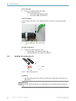
Check the red mark (sample gas line) and the blue mark (instrument air line)
match the connections on the sample gas cooler (see Operating Instructions,
Chapter “Removing and fitting the sampling probe”).
9.
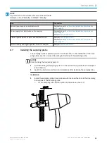
Screw the frame tight (1.5 Nm).
10. Screw the clamping screws tight (1.5 Nm).
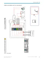
11. Electrical connection: See the wiring diagram on the inside of the terminal box
cover.
°
Core cross-section: 1.5 mm
2.
°
Connections: BK 1, BK 2, GNYE: See identification rings on the crimp lead
end sleeves.
2.9
Installing the sample conditioning
2.9.1
Fitting the sample conditioning
Figure 8: Sample conditioning (exterior view)
Figure 9: Sample conditioning (interior view,
the sample gas cooler is system-specific)
1
Enclosure duct for heated sample gas line
2
Sample gas cooler with hose pump
3
Cooler sample gas inlet (inlet of heated sample gas line)
2
INSTALLATION
24
T E C H N I C A L I N F O R M A T I O N | MARSIC200
8017324/15A2/V6-0/2019-10 | SICK
Subject to change without notice


