b
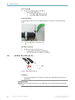
Make sure the condensate is safely collected or drained off.
b
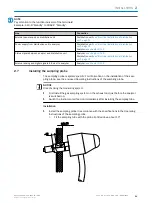
The hose end can end max. 10 m above the condensate outlet.
2.9.3
Electrical installation of sample conditioning
1
Terminal box
b
Lay the electric lines through the enclosure openings.
b
Connect the electric lines.
°
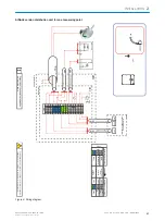
For the circuit diagram, see the attached system documentation and inside
the cover of the terminal box.
Electric line
Connect to:
Power supply from distribution unit
See enclosed system documentation
Power supply to sampling probe
Cooler and probe status on distribution unit
Control signals to sample conditioning from distribu‐
tion unit
“Heating” status from sampling probe
Enclosure grounding optional
2.10
Installing the distribution unit
View
MULTI version distribution unit for two to four measuring points (example)
Figure 10: Distribution unit (exterior view)
Figure 11: Distribution unit (interior view sys‐
tem-specific)
INSTALLATION
2
8017324/15A2/V6-0/2019-10 | SICK
T E C H N I C A L I N F O R M A T I O N | MARSIC200
27
Subject to change without notice


