


2.10.3
Electrical installation of distribution unit
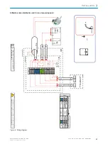
Figure 15: SINGLE version distribution unit for
one measuring point (example)
1
Terminal strips
2
Grounding
b
Lay the electric lines through the enclosure openings.
b
Connect the electric lines.
°
For the circuit diagram, see the attached system documentation and inside
the cover of the terminal box.
Electric line
Signal
Connect to:
External power supply
See the wiring diagram in the system documentation
Power supply to sample conditioning
See the wiring diagram in the system documentation
Power supply to analyzer
See the wiring diagram in the system documentation
Status signals from sample conditioning
DI
Sampling probe and cooler
See the wiring diagram in the system documentation
Control signals to sample conditioning
DO
See the wiring diagram in the system documentation
Signal lines to/from analyzer
DI
See the wiring diagram in the system documentation
DO
See the wiring diagram in the system documentation
AI
See the wiring diagram in the system documentation
AO
See the wiring diagram in the system documentation
Signal lines to/from external
DI
See the wiring diagram in the system documentation
Optional for stand-by operation
DO
See the wiring diagram in the system documentation
Maintenance and status
AI
See the wiring diagram in the system documentation
optional
AO
See the wiring diagram in the system documentation
Meas. values
Enclosure grounding
Inside, bottom right.
b
Install an external power disconnection unit which disconnects all connectors and
fuses near the analyzer. The power disconnection unit must have a unique mark‐
ing and be easily accessible.
Observe the max. power input of the complete system:
.
INSTALLATION
2
8017324/15A2/V6-0/2019-10 | SICK
T E C H N I C A L I N F O R M A T I O N | MARSIC200
31
Subject to change without notice


