4
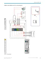
Sample conditioning with:
•
Sample gas cooler
•
Solenoid valve for feeding instrument air/test gas to the sampling probeTest gas feed
5
Gas inlets of sample conditioning:
•
Instrument air to backflush the probe
•
Only possible for measuring point 1: Test gas for adjustment via probe (optional)
6
Unheated sample gas line, sample conditioning - distribution unit
7
Lines, sample conditioning - distribution unit:
•
Power supply of sample conditioning
•
Signal line
8
Distribution unit with:
•
Power supply, complete system with central power distribution
•
System fuses
•
Main switch
•
“Stand-by” switch
•
Flow indicator
•
Sample gas fine filter
•
Water trap
•
Sample gas pump
•
Sample gas valve (test gas feed optional)
•
Measuring point switchover (for 2 ... 4 measuring points)
•
Bypass pump (for 2 ... 4 measuring points)
9
Inlet for central power supply for the complete system
•
The distribution unit provides electrical power for all system modules.
ß
Unheated sample gas line from distribution unit to analyzer
à
Lines, distribution unit - analyzer:
•
Analyzer power supply
•
Signal lines
á
Analyzer
•
Control unit
•
Measuring modules:
°
Gas module (flow, humidity and pressure)
°
DEFOR (NO, NO
2
and SO
2
)
°
FINOR (CO
2
)
°
OXOR (O
2
), option
•
Analog and digital interfaces
•
Ethernet
â
Sample gas outlet
ã
Test gas inlet
Test gas connection during adjustment
ä
Condensate outlet
å
Signal lines/Ethernet to periphery
2
INSTALLATION
12
T E C H N I C A L I N F O R M A T I O N | MARSIC200
8017324/15A2/V6-0/2019-10 | SICK
Subject to change without notice


