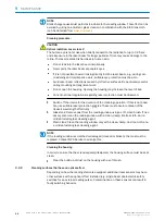
NOTE
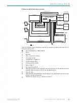
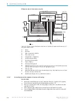
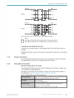
The SOPAS ET configuration software can be used to configure the debounce time.
•
Min.: 0 ms
•
Max.: 10,000 ms
•
Default: 10 ms
In areas with strong electromagnetic radiation, debounce times of < 10 ms can cause
undesired status changes to the switching input of the device (e.g. unintended initiation
of the reading process).
In order to avoid undesired status changes, the following measures are recommended:
•
Keep the length of cables from the signal source to the device as short as possible
•
Reduced coupling to adjacent cables
•
Shielding of influenced cables
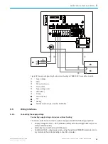
Signal
3
3.32K
6.64K
"
§
$
Sensor GND
V
S
2
V
S
V
S
V
in
5
!
PNP sensor
1
GND
Switching input
4
GND
V
S
Figure 40: Wiring of a switching input with external PNP sensor
1
PNP sensor
2
Supply voltage V
S
= U
V
3
Input signal
4
Switching input (“Sensor 1” or “Sensor 2”)
5
Input voltage V
in
!
...
$
For pin assignment, see respective device
Extension: additional logical switching inputs in the device in the case of physical
“external” switching inputs on the optional connection module
Thanks to the optional CMC600 parameter memory module, the two external switching
inputs “External input 1” and “External input 2” on the relevant terminals in the connec‐
tion module are additionally available.
NOTE
These two external switching inputs are not suitable for time-critical applications.
If the wiring of the inputs is carried out via a connection module, the respective operat‐
ing instructions for the module are to be observed.
6
ELECTRICAL INSTALLATION
54
O P E R A T I N G I N S T R U C T I O N S | CLV63x, CLV64x, CLV65x
8019588/129Z/2019-02-07 | SICK
Subject to change without notice


