


Ethernet version, 17-pin male connector
“V
S
”
“Host 1”
“Aux 1”
“Result 2”
“Result 1”
“CAN”
“Sensor 2”
“Sensor 1”
“AUX”
CAN bus
“Result 1”
“Result 2”
PLC
CDB650-204
Connection module
4
“Host 1”
“Aux 1”
RS-232
HOST/PLC
Further data
processing
6
PC
Configuration
Diagnostics
5
Interfaces
2
“Ethernet” (Host 2/Aux 2)
“USB” (Aux 3)
3
RS-232/422
Ethernet
USB
“Host 2”
Ethernet
“Aux 2”
“Aux 3”
“Sensor 2”
“Sensor 1”
“External input 2”
“External input 1”
CMC600
â
á
à
V
S
8
=
ß
“External output 2”
“External output 1”
Device
1
9
7
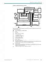
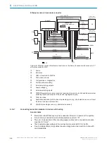
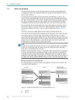
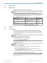
Figure 36: Ethernet version: Electrical connections on the bar code scanner with connector, 17-
pin male connector, M12
1
Device
2
Interfaces
3
USB not required for CLV62x
4
Connection module
5
Configuration or diagnostics
6
Further data processing
7
External switching outputs
8
Supply voltage V
S
9
External switching inputs
ß
CMC600 parameter memory module is required to be able to use the additional external
switching inputs and outputs of the device (highlighted in gray)
à
Other functions
á
Application-dependent alternative stop reading cycle (e.g., photoelectric sensor) or travel
increment (incremental encoder)
â
Start/Stop reading sensor (e.g., photoelectric sensor)
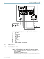
6.5.2
Connecting connection modules to devices with heating
General notes
■
Electrical connections may only be made when there is no power in the system.
■
Do not do any connection work at temperatures under 0 °C!
■
The wire cross section of the incoming supply cables to the connection module
must be 0.75 mm
2
.
■
The required supply voltage at the connection module is DC 24 V ±10%.
■
Due to voltage drops, long cables require a larger wire cross section in line with
valid standards.
6
ELECTRICAL INSTALLATION
48
O P E R A T I N G I N S T R U C T I O N S | CLV63x, CLV64x, CLV65x
8019588/129Z/2019-02-07 | SICK
Subject to change without notice


