7.3
Initial commissioning
The user adjusts the device to the reading situation on location using the SOPAS-ET
configuration software. During this, the device is usually connected directly to the PC/
laptop (online method).
The starting point for adjustment during the initial commissioning is a copy of the
device’s factory default settings in the working memory with predefined parameter val‐
ues. Each of the parameter values can be changed within their value range to optimize
the device. An application-specific, new parameter set is created with the SOPAS ET
configuration software as a result, provisionally only in the device’s working memory.
After testing the desired functionality in read mode, the parameter set created can be
permanently saved on the device. The factory default settings cannot be overwritten
and remain available at all times in case the device needs to be reset (
).
The device can only save
one
application-specifically created parameter set.
If the effects of various parameter variations need to be tested on the read mode, then
they must be saved in a further parameter set under another file name on the PC/
laptop. Then download these parameter sets one after another for testing on the device
without permanently saving them. Each download overwrites the previously transferred
parameter set in the working memory. Only the last parameter set to be set is then
finally saved on the device with the “Permanent” option.
NOTE
As part of a structured data security concept, it is recommended to save, and therefore
archive, the current parameter set using a project file (Sopas file with configuration
data) under a meaningful name on the PC.
External, optional parameter memory components outside of the device’s internal para‐
meter memory allow for direct parameter cloning. In case of defects, it is possible to
exchange the device quickly without losing configuration data. The storage media are
available for this, depending on the device, are microSD memory cards for the device or
the parameter cloning module CMC600 for the connection module CDB and/or CDM.
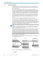
Memory organization for parameter set
The following diagram shows the memory management principle for the involved inter‐
nal and external components:
Parameter set in the
main memory of the
device
8
Permanently saved
parameter set of the
device
5
Factory default setting of
the device
9
Device
2
Optional:
1
PC with SOPAS ET
Configuration Software
3
MicroSD memory card
4
Parameter memory module
CMC600
7
Volatile memory
â
Opened project file
with current parameter
set of the device
ß
Volatile memory
â
Non-volatile memory
á
Non-volatile memory
á
Saved project file (*.sopas)
with archived parameter
set of the device
à
Data base on e. g. hard drive
(non-volatile memory)
ã
‒ and/or ‒
6
Permanently saved
parameter set of the
device
5
Non-volatile memory
á
Permanently saved
parameter set of the
device
5
Non-volatile memory
á
Figure 41: Configuration with SOPAS ET and saving the parameter set
1
Optional
2
Device
7
COMMISSIONING
56
O P E R A T I N G I N S T R U C T I O N S | CLV63x, CLV64x, CLV65x
8019588/129Z/2019-02-07 | SICK
Subject to change without notice


