background image


92 

4. Parameter description 

Parameter 

4.38


Slip compensation coefficient (P.89)                                                                                 

P.89 

Slip compensation coefficient


We can make the speed of the motor, which runs with rated current, to be much closer to the setting 

speed by setting this parameter properly.   


Parameter 

Factory 

setting 

Setting 

range 

Remarks 

slip compensation is forbidden 

89 

0~10 

10 

compensation value is 3% of the target frequency 


4.39 Frequency jump (P.91~P.96)                                                                           

P.91~P.96 

Frequency jump


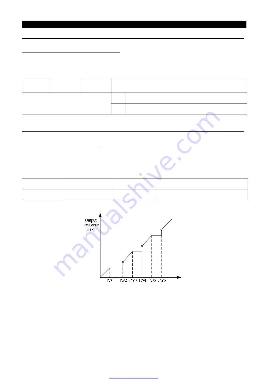
  To  avoid  the  system  mechanical  resonance  frequency,  3  sets  of  jump  frequencies  are  presented 

namely, the first by P.91 and P.92 , the second by P.93 and P.94 and the last by P.95 and P.96. 


Parameter 

Factory setting 

Setting range 

Remarks 

91

96 

Frequency jump 

0~400Hz

99999 

99999, invalid 


<Setting>


For example: suppose that P.91 = 45 and P.92 = 50 

If the target frequency 

 45Hz, the steady output frequency = the target frequency.   

If 45Hz < target frequency 

 50Hz

, the steady output frequency = 45Hz.   

If 50Hz < target frequency, the steady output frequency = the target frequency. 


PDF created with pdfFactory trial version 

www.pdffactory.com

Содержание SF Series

Страница 1: ...signal is called target frequency When the motor starts running the output frequency of the inverter will gradually accelerate to the target frequency and finally run steadily at the target frequency The output frequency at this time is called steady output frequency 2 There are detailed instructions on parameter settings in Chapter 4 In case users are not familiar with these settings arbitrary ad...

Страница 2: ...al two words on and turn on are often used The on is used to indicate that the external switch of the terminal is in close state and thus belongs to the description of the state The turn on is employed to describe the action that the external switch of the terminal is shut on from the open state to the close state and thus belongs to the description of action PDF created with pdfFactory trial vers...

Страница 3: ...he package Please check whether it is damaged during transport Please check whether the inverter type is identical with which shown on the package 1 1 Nameplate instruction Output 13A MAX 3PH AC380 480V 5 5KW Input 14A 3PH AC380 480V 50 60Hz Style No SF 040 5 5K Serial NO MFG NO L2L0072 FN00001 FREQ Range 0 2 400Hz IP20 1 2 Type instruction PDF created with pdfFactory trial version www pdffactory ...

Страница 4: ...Power supply Power source capacity kVA 12 17 20 28 34 41 52 65 79 99 Cooling method Forced air cooling Weight kg 5 6 5 6 7 0 8 3 9 0 20 21 37 37 37 2 1 2 440V Series Three Phase Model SF 040 K 5 5 7 5 11 15 18 5 22 30 37 HP 7 5 10 15 20 25 30 40 50 applicable motor capacity kW 5 5 7 5 11 15 18 5 22 30 37 Rated output capacity kVA 10 14 18 25 29 34 46 56 Rated output current A 13 18 24 32 38 45 60 ...

Страница 5: ...ge 3 Phase 380 480V 50Hz 60Hz Power voltage permissible fluctuation 3 Phase 342 528V 50Hz 60Hz Power frequency permissible fluctuation 5 Power supply Power source capacity kVA 79 100 110 137 165 198 247 Cooling method Forced air cooling Weight kg 25 37 37 37 67 67 67 Note The test condition of rated output current rated output capacity and frequency converterinverter power consumption is the carri...

Страница 6: ...celeration curve model can be selected P 29 DC braking The DC braking action frequency is 0 120Hz P 10 the DC braking time is 0 10 Seconds P 11 and the DC braking voltage is 0 30 P 12 Linear braking and Idling braking selection P 71 Stalling protection The stalling protection level can be set to 0 200 P 22 Target frequency setting Operation panel setting DC 0 5V signal setting DC 0 10V signal sett...

Страница 7: ...unication and Shihlin Modbus protocol to selection Protection mechanism Alarm function Output short circuit protection Over current protection P N over voltage protection voltage too low protection motor over heat protection P 9 IGBT module over heat protection braking transistor abnormality protection communication abnormality protection etc Ambient temperature 10 40 non freezing Ambient humidity...

Страница 8: ...0 5 5 18 5K SF 040 5 5 22K Model L mm L1 mm W mm W1 mm H mm SF 040 5 5 7 5K 323 303 200 186 186 SF 020 5 5 7 5 11K 323 303 200 186 186 SF 040 11 15K 323 303 200 186 186 SF 020 15 18 5K 350 330 230 214 195 SF 040 18 5 22K 350 330 230 214 195 PDF created with pdfFactory trial version www pdffactory com ...

Страница 9: ...and wait 10 minutes before removing this cover Ensure proper earth connection CAUTION Risk of fire Mountthe inverter on a non com bustible surface 危險 有受 傷 感 電之 虞 安 裝運 轉之 前請 詳讀 說明 書 並 依指 示操 作 通電 中及 電源 關閉 後10分鐘 內 請 勿打 開上 蓋 請確 實接 地 注意 有發 生火 災之 虞 請安 裝於 金屬 等不 燃物 之上 7 7 W1 W L1 L 2 7 H Model L mm L1 mm W mm W1 mm H mm SF 020 22 30K 379 348 271 236 248 PDF created with pdfFactory trial version www pdffac...

Страница 10: ...61 510 300 277 220 270 9 SF 040 55K 595 566 370 336 336 286 13 SF 020 37K 595 566 370 336 336 286 13 SF 040 75K 595 566 370 336 336 286 13 SF 040 90K 595 566 370 336 336 286 13 SF 020 45K 595 566 370 336 336 286 13 SF 020 55K 850 821 425 381 381 286 13 SF 040 110K 850 821 425 381 381 286 13 SF 040 132K 850 821 425 381 381 286 13 SF 040 160K 850 821 425 381 381 286 13 PDF created with pdfFactory tr...

Страница 11: ...el Output 13A MAX 3PH AC380 480V 5 5KW Input 14A 3PH AC380 480V 50 60Hz Style No SF 040 5 5K Serial NO MFG NO L2L0072 FN00001 FREQ Range 0 2 400Hz IP20 2 4 2 SF 020 5 5 18 5K SF 040 5 5 22K 1 Push and lift the latch of top cover to remove top cover PDF created with pdfFactory trial version www pdffactory com ...

Страница 12: ...s with terminals please use cable to tie the wires in a bundle 2 4 3 SF 020 22 30K 1 Push and lift the latch of top cover to remove top cover 2 Wiring Outlet hole is designed for fixing and protecting the lead wire When wiring lead wire must pass thru wiring outlet hole and then connects with terminals please use cable to tie the wires in a bundle PDF created with pdfFactory trial version www pdff...

Страница 13: ...let hole is designed for fixing and protecting the lead wire When wiring lead wire must pass thru wiring outlet hole and then connects with terminals please use cable to tie the wires in a bundle 2 4 5 Each type of main loop terminals arrangement l terminal arrangement Note 1 SF 020 5 5 7 5 11K SF 040 5 5 15K PDF created with pdfFactory trial version www pdffactory com ...

Страница 14: ...Inverter 2 SF 020 15 18 5K SF 040 18 5 22K 3 SF 020 22 30K 4 SF 020 37 55K SF 040 30 160K l DC reactor connection Note SF 020 22 55kW and SF 040 55 160kW series inverters have internal DC reactor PDF created with pdfFactory trial version www pdffactory com ...

Страница 15: ...W and SF 040 55 160kW series inverters do not have internal DC reactor the user can select the brake unit or brake resistance SF 020 5 5 18 5kW and SF 040 5 5 22kW series inverters have internal DC reactor the user can select the brake resistance PDF created with pdfFactory trial version www pdffactory com ...

Страница 16: ...istic easy degradation 4 Inverter installed in the control device or the plate when not used in construction which especially the extra humid and dust inverter should been remove move put in accordance with the above mentioned storage conditions appropriate environments 5 The electrolytic capacitors is long term no electricity the characteristic easy degradation Do not place in the no state electr...

Страница 17: ...s value of conduction and radiation which CE declared In the input and output terminal increased the ferrite lateral auxiliary will be better effect 3 Shield Good shielding and grounding can greatly reduce the interference of inverter and can improve the anti interference ability of the inverter Using the good conduct electricity sheet metal sealing and let the sheet metal grounding can satisfy th...

Страница 18: ...at places with airborne oil mist and dust 8 Please do not install the inverter at places exposed to corrosive gas salt laden air 9 Please do not install the inverter in the environment of high temperature and high humidity Note 1 Only qualified electrical professional personnel can carry out the installation wire arrangement dismounting and maintenance 2 Please ensure to comply with the installati...

Страница 19: ...19 2 Introduction of Shihlin Inverter Introduction of Inverter 2 5 5 System wire arrangement of SF 020 5 5 55K SF 040 5 5 160K series PDF created with pdfFactory trial version www pdffactory com ...

Страница 20: ...gauge wires are main circuit wires the rest are control circuit wires 2 For the usage of external thermal relay please refer to P 80 P 84 P 86 P 126 P 128 in Chapter 4 3 Make sure do not to short PC and SD 4 The DC reactor between Pand P1 can be selected If the DC reactor is not selsected please short P and P1 PDF created with pdfFactory trial version www pdffactory com ...

Страница 21: ... multi function control terminal it is all of its outside wire arrangement can be considered as a simple switch If the switch is on the control signal will be put into the terminal if the switch is off the control signal is shut off If Sink Input mode is selected the function of the terminal is active when it is shorted with SD or connected with the external PLC In this mode the current flows out ...

Страница 22: ...tion caused by leakage current Source Input the multi function control terminal is connected with open emitter PLC and external power supply PLC I STF STR PC Inverter DC 24V SD DC 24V Main circuit terminals Terminal name Remarks R S T Connect to the commercial power supply U V W Connect to three phase squirrel cage motor P P1 Connect to DC reactor P PR Connect to braken resistors Note1 2 P N Conne...

Страница 23: ...can effectively dissipate the feedback energy from the motor to the inverter when decelerating In case there is any problem on purchasing of the brake unit please feel free to contact us 4 For safety and reduce noise grounding terminals of inverter must to be good grounded To avoid electric shocks and fire accident external metal wire of electrical equipment should be short and thick and it should...

Страница 24: ...y P 38 4 The input point of current signal 4mA 20mA is used to set the target frequency P 39 Analog signal input 5 The common reference ground of 2 4 10 and FM AM A B Relay output C Normally points A C are always open circuit and points B C are always short circuit please refer to P 85 in Chapter 4 SU RUN FU Optional The terminal can also be called multi function output terminal The function name ...

Страница 25: ...wire shall not exceed 500 meters 6 Pressing connection terminals with insulated sleeve shall be utilized for the wiring at the power source side and the load side 7 In a short period after the power supply is shut off high voltage still exists between the terminals P N thus please do not touch them within 10 minutes to avoid personnel electric shock Control circuit wire arrangement 1 For wiring of...

Страница 26: ...ry out the installation wire arrangement dismounting and maintenance 3 Please comply with the wire arrangement notice In case the installation has not been fully complied with and damage of the inverter or dangerous accidence thus be resulted in our company will not undertake any legal responsibility In case there is any question on the wire arrangement please feel free to contact us PDF created w...

Страница 27: ...r applying power to the inverter do not cut off the Mini jumper Therefore please make sure that main power has been switched off before cutting off the Mini jumper 2 The gap discharge may occur when transient voltage is high than 1000V Besides electro magnetic compatibility of the inverter will be lower after cutting the Mini jumper 3 Do not cut the Mini jumper when main power is grounded To preve...

Страница 28: ...9 KVA NF400 300A S P180 SF 020 55K 220V 75HP 99 KVA NF400 350A S P220 SF 040 5 5K 440V 7 5HP 11 5 kVA NF30 30A S P21 SF 040 7 5K 440V 10HP 16 kVA NF30 30A S P21 SF 040 11K 440V 15HP 20 kVA NF50 50A S P30T SF 040 15K 440V 20HP 27 kVA NF100 60A S P40T SF 040 18 5K 440V 25HP 32 kVA NF100 75A S P40T SF 040 22K 440V 30HP 41 kVA NF100 100A S P50T SF 040 30K 440V 40HP 52 kVA NF225 125A S P50 SF 040 37K 4...

Страница 29: ...20 18 5K 38 30 38 30 38 6 38 6 SF 020 22K 38 30 38 30 38 6 38 6 SF 020 30K 60 200 60 200 60 8 60 8 SF 020 37K 80 200 80 200 80 8 80 8 SF 020 45K 100 200 100 200 100 10 100 10 SF 020 55K 100 200 100 200 100 10 100 10 SF 040 5 5K 3 5 30 2 18 5 5 4 2 4 SF 040 7 5K 3 5 30 3 5 30 5 5 4 5 5 4 SF 040 11K 5 5 30 5 5 30 5 5 6 5 5 6 SF 040 15K 14 30 8 30 14 6 8 6 SF 040 18 5K 14 30 8 30 14 6 8 6 SF 040 22K ...

Страница 30: ...bove SF 020 55K 19200W 2 5Ω and above SF 040 110K 21600W 4Ω and above SF 040 5 5K 1000W 75Ω and above SF 040 132K 21600W 4Ω and above Note 1 The brake resistor capacity listed in the above table is based on the condition that the regenerative brake duty is 10 that is in case braking lasts for 5 seconds another 45 seconds must be provided for heat dissipation The brake resistor wattage can be reduc...

Страница 31: ... 08 0 14 45 60 180 250 0 065 0 11 55 75 220 250 0 065 0 11 3 Phase 440V 50 60Hz Inductance mh kW HP Rated Amps of inverter Rated Amps of reactor 2 impedance 4 impedance 5 5 7 5 13 15 1 1 9 7 5 10 18 20 0 75 1 4 11 15 24 30 0 6 0 93 15 20 32 40 0 42 0 7 18 5 25 38 50 0 35 0 56 22 30 45 60 0 28 0 47 30 40 60 80 0 19 0 35 37 50 73 90 0 19 0 31 45 60 91 120 0 13 0 23 55 75 110 150 0 11 0 19 75 100 150...

Страница 32: ... 60 180 250 0 028 0 055 55 75 220 250 0 028 0 055 3 Phase 440V 50 60Hz Inductance mh kW HP Rated Amps of inverter Rated Amps of reactor 1 impedance 2 impedance 5 5 7 5 13 15 0 47 0 93 7 5 10 18 20 0 35 0 7 11 15 24 30 0 23 0 46 15 20 32 40 0 18 0 35 18 5 25 38 50 0 14 0 28 22 30 45 60 0 12 0 23 30 40 60 80 0 087 0 17 37 50 73 90 0 078 0 17 45 60 91 120 0 058 0 11 55 75 110 150 0 047 0 09 75 100 15...

Страница 33: ... 180 0 33 55 75 250 0 26 3 Phase 440V 50 60Hz kW HP DCAmps Inductance mh 5 5 7 5 12 6 3 7 5 10 23 3 6 11 15 33 1 9 15 20 40 1 26 18 5 25 50 1 08 22 30 33 1 9 30 40 40 1 26 37 50 78 0 72 45 60 95 0 54 55 75 115 0 45 75 100 160 0 36 90 120 180 0 33 110 150 250 0 26 132 175 340 0 26 160 215 340 0 18 Note SF 020 22 55kW and SF 040 55 160kW series inverters have internal DC reactor user can install AC ...

Страница 34: ... 097 22001 XX 3 Phase 440V 50 60Hz kW HP Rated Amps of inverter Types of filter 5 5 7 5 13 096B 02001 00A 7 5 10 18 096B 02001 00A 11 15 24 096B 04001 00A 15 20 32 096B 04001 00A 18 5 25 38 096B 04001 00A 22 30 45 096B 05001 00A 30 40 60 096B 10001 00 37 50 73 096B 10001 00 45 60 91 096B 10001 00 55 75 110 096B 18001 00 75 100 150 096B 18001 00 90 120 180 096B 18001 00 110 150 220 097 31001 XX 132...

Страница 35: ...e key or on the DU01 operation panel External voltage current signal combination of multi speed stage levels or External JOG External terminals 0 External mode Frequency of each section in Programmed operation mode P 131 P 138 External terminal STF The PU mode External mode and JOG mode are valid and interchangeab le PU mode Equal to the PU mode when P 79 0 1 JOG mode Equal to the JOG mode when P ...

Страница 36: ... P 15 External terminals 7 Combined mode 4 External voltage current signal or combination of multi speed stage levels Communication Operation mode selection P 79 8 Combined mode 5 DU01 operation panel combination of multi speed stage levels or external JOG P 15 External terminals If P 79 0 the inverter is in external mode when it is started and the operating mode can be shifted by setting P 79 PDF...

Страница 37: ...r 5 the indicating lamp will be flickered 4 In JOG mode the indicating lamp will be lit and at the same time the display screen will display while the motor is not running 5 If Pr79 2 3 4 5 6 7 or 8 the operation mode will be constant so there are no flow charts for it 3 2 Working modes of a operation panel The Du01 operation panel can be used to monitor the output frequency output current and out...

Страница 38: ...ng mode with DU01 Note 1 When in monitoring output frequency mode the indicating lamp of and will be lit and at the same time the screen will display the current output frequency 2 When in monitoring output voltage mode the indicating lamp of and will be lit and the screen will display the current output voltage value 3 When in monitoring output current mode the indicating lamp of and will be lit ...

Страница 39: ...ng and 2 In the frequency setting mode the indicating lamp will be lit but will not be lit 3 When setting frequency in PU mode the set value can not exceed the upper frequency When high frequency is needed the upper frequency should be changed first 3 2 4 The operating flow charts for parameter setting mode with DU01 PDF created with pdfFactory trial version www pdffactory com ...

Страница 40: ... lit Note 1 When P 79 0 after the power is switched on or the inverter is reset the inverter will enter external mode first 2 For selection and shifting of operation modes please refer to Section 3 1 2 Enter frequency setting mode and write the target frequency into the memory Note For the detailed setting procedure please refer to Section 3 2 3 Press or then the motor will run At this time the in...

Страница 41: ... in Chapter 4 2 For the operating procedure of the monitoring mode please refer to Section 3 2 3 If programmed operation mode is chosen STF becomes starting signal and STR becomes pause signal they are not Run Forward or Run Reverse terminals anymore 4 Turn off STF or STR and the motor will decelerate till it stops The indicating lamp of will not turn off until the inverter has stopped putting out...

Страница 42: ...til the inverter has stopped putting out voltages 3 8 The basic operation procedure for Combined mode 2 P 79 5 Steps Description 1 In Combined mode 2 the indicating lamp of will flicker Note For selection and shifting of the operation mode please refer to Section 3 1 2 The target frequency is set by external terminals If the target frequency is set by the input signal across terminal 4 5 please re...

Страница 43: ...8 When EXJ is on the target frequency is determined by the set value of P 15 Acceleration deceleration time is set by the value of P 16 The inverter starting is determined by external terminals 3 12 Operation 3 12 1 Check and preparation before operation Before the start of operation shall examine the following several aspects 1 Check the wiring is ture or not Especially check ac motor driver outp...

Страница 44: ...ower is lit 2 Please pick a switch between STF and SD or STR and SD 3 Please pick a potentiometer among 2 5 10 or provide 0 5V dc between 2 and 5 4 Please adjust potentiometer or 0 5V dc a minimum value under 1V 5 If STF on forward rotation if STR on reverse rotation Turn off STF or STR and the motor will decelerate till it stops 6 Ensure the following several aspects 1 Motor rotation direction is...

Страница 45: ... shall be stopped working immediately and according to the fault diagnosis check anomalies causes After inverter stop output but the power terminal R S T of main circuit is not disconnected if you touching the output terminals U V W of inverter may occur shock Otherwise even cut off major loop power because the filter capacitor has recharging voltage discharge end need some time After cut off majo...

Страница 46: ...ve 0 30 46 99999 0 30 99999 99999 function invalid Setting If P 0 6 and P 19 220V and when output frequency of the inverter is 0 2Hz the output voltage is If RT is on P 46 Second Torque Boost is valid Note 1 If the set value of P 0 is too high it will result in the action of the current protection of the inverter or the inverter will be disabled to start smoothly 2 The Second Function is valid onl...

Страница 47: ...requency P 1 P 18 the steady output frequency equals target frequency If P 1 P 18 target frequency the steady output frequency equals P 1 Note 1 The maximum frequency and the high speed maximum frequency are related with each other If the target upper limit frequency is in the range of 0 120Hz P 1 must be used the setting range of P 1 is 0 120Hz if the target upper limit frequency is in the range ...

Страница 48: ... 1 400Hz When P 189 0 19 99999 0 1000V 99999 220V series inverters factory setting is 220 440V series inverters factory setting is 440 99999 function invalid 47 99999 0 400Hz 99999 function invalid P 3 P 47 Output frequency Output voltage V P 19 Setting The Base Frequency is set through P 3 and P 47 If RT is on P 47 Second Base Frequency is valid Note 1 The Base voltage is set through P 19 Note 2 ...

Страница 49: ...function terminals selection Parameter Factory setting Setting range Remarks 4 60Hz 0 400Hz 5 30Hz 0 400Hz 6 10Hz 0 400Hz 24 27 99999 0 400Hz 99999 99999 is not chosen 142 0Hz 0 400Hz 143 149 99999 0 400Hz 99999 99999 is not chosen Setting If all the setting values of P 24 P 27 and P 142 P 149 are not 99999 16 speed operation is active It means that with the combination of RL RM RH and REX there a...

Страница 50: ...he multi function control terminal For example P 80 2 RL terminal is chosen to perform the RL function Please refer to P 80 P 84 P 86 P 126 P 128 for multi function selection and refer to section 2 5 for wiring 4 5 Acceleration deceleration time P 7 P 8 P 20 P 21 P 44 P 45 P 7 Acceleration time P 8 Deceleration time P 20 Acceleration deceleration reference frequency P 21 Acceleration deceleration ...

Страница 51: ...he second function is disabled In this case even though RT is on the acceleration time is still the set value of P 7 and the deceleration time is still the set value of P 8 the torque boost is still the set value of P 0 and the base frequency is still the set value of P 3 If P 44 99999 and P 45 99999 when RT is on the acceleration deceleration time is the set value of P 44 If P 44 99999 and P 46 9...

Страница 52: ...thermal relay to each motor 3 When a special motor is employed the electronic thermal relay is no longer valid Install an external thermal relay to each motor 4 About wiring for an external thermal relay refer to P 80 P 84 P 86 P 126 P 128 4 7 DC injection brake P 10 P 11 P 12 P 10 DC injection brake operation frequency P 11 DC injection brake operation time P 12 DC injection brake voltage Paramet...

Страница 53: ...racteristics 4 8 Starting frequency P 13 P 13 Starting frequency When the motor starts up the instant output frequency of the inverter is called starting frequency Parameter Factory setting Setting range Remarks 13 0 5Hz 0 60Hz Setting If the target frequency of the inverter islower than the setting value of P 13 the motor will not run When the signal of the motor start the output frequency will g...

Страница 54: ... of different VF curve Setting If P 14 4 suppose that P 19 220V P 98 5HZ P 99 10 when the inverter is running at 5HZ the output voltage equals P 99 P 19 10 220V 22V If RT is on P 46 Second Torque Boost is valid P 14 0 Applicable to Constant torqueloads conveyer belt etc P 14 1 Applicable to Variabletorqueloads fans and pumps etc PDF created with pdfFactory trial version www pdffactory com ...

Страница 55: ...torque is due to the set values Note 1 P 14 5 Output frequency P 0 0 P 3 P 19 A P 98 3 0 0 1 When P 14 5 The value of A is 7 1 Note 2 P 14 6 7 8 P 0 0 P 3 P 19 A 3 0 Output frequency 0 1 When P 14 6 the value of A is 8 7 when P 14 7 the value of A is the value of A is 10 4 when P 14 8 the value of A is 12 0 Note 2 P 14 9 10 P 0 0 P 3 P 19 A 30 0 1 Output frequency When P 14 9 the value of A is 20 ...

Страница 56: ...P 99 P162 P 163 P164 P 165 like this set every last 2 If you set value of P 14 from 5 to 13 the curve will invalid when the value of P 0 is larger than the value of A it will be equivalent to the cueve when P 14 0 4 10 JOG mode P 15 P 16 P 15 JOG frequency P 16 JOG acceleration deceleration time In JOG mode the output frequency is the set value of P 15 and the acceleration deceleration time is the...

Страница 57: ...6 Stall prevention operation level reduction starting frequency With a heavy load in the case when a motor starts or the target frequency is adjusted increasing the motor speed often can not tightly follow the output frequency If the motor speed is lower than the output frequency the output current will increase to improve the output torque However if the difference between the output frequency an...

Страница 58: ...output current of the inverter will increase Once the output current exceeds the upper limit pre set as the following figure the adjustment of the output frequency is paused automatically and will continue to proceed until the motor captures the output frequency at this moment the output current of the inverter will decrease correspondingly P 24 P 27 Please refer to P 4 P 5 P 6 4 12 Output frequen...

Страница 59: ...ncrease If the set value of P 28 is 0 the filtering function is invalid Parameter Factory setting Setting range Remarks 28 0 0 31 4 13 Acceleration deceleration pattern selection P 29 P 29 Acceleration deceleration pattern selection Parameter Factory setting Setting range Remarks 29 0 0 2 Setting When P 29 0 Linear acceleration deceleration curve An acceleration slope is constructed by combination...

Страница 60: ...licable to main shafts of the working machines When P 29 2 S pattern acceleration deceleration curve 2 An acceleration slope is formed by combination of P 7 and P 20 A deceleration slope is formed by combination of P 8 and P 20 When the target frequency varies it increases with the acceleration slope or decreases with the deceleration slope As shown in the figure below when the setting value of th...

Страница 61: ...egenerative brake duty The Higher the regenerative brake duty is the more energy the brake resistor consumes and the stronger the brake capability is Parameter Factory setting Setting range Remarks 0 If regenerative brake duty is 3 fixedly the value of parameter 70 is failure 30 0 0 1 1 The regenerative brake duty is the value witch parameter 70 setting 70 0 0 30 Note 1 In occasions where frequent...

Страница 62: ...rters have two communication protocols to selection Shihlin protocol and Modbus protocol If the communication expansion board is selected the corresponding communication protocol is provided P 32 P 36 P 52 P 53 and P 153 are applied to both of the protocols P 48 P 51 is only applied to the Shihlin protocol and P 154 is only applied to Modbus protocol Parameter Factory setting Setting range Remarks...

Страница 63: ...ers witchthe communication interface enables a host computer to control is due to the wiring mothed and impedance matching Once Modbus protocol is selected please set P 33 to nonzero value 2 If the time of communication error exceeds the set value of P 52 and P 153 is set to 0 an alarm will be output and the screen of DU01 will display 3 When P 53 99999 there is no time limit 4 Modbus protocol Pro...

Страница 64: ...n 3 2 for detailed operation of the operation panel working mode 3 When the output mechanical speed is more than 99998 the screen will display 99999 4 18 Voltage signal selection and target frequency P 38 P 73 P 139 P 140 P 141 P 38 The maximum output Frequency the target frequency is set by the input signal across terminal 2 5 P 73 Voltage signal selection P 139 Voltage signal bias P 140 Voltage ...

Страница 65: ... 10V 139 0 00 0 00 200 0 140 100 0 0 10 200 0 141 0 0 11 Setting There are 2 digits in P 141 every digit have the different meaning relevant positions as following Now let s see some examples Example 1 This is the most used setting When the inverter is in external mode combined mode 2 or combined mode 4 and the frequency is set by terminal 2 5 Parameter setting P 38 60 00Hz P 73 1 P 139 0 P 140 10...

Страница 66: ... not increase the output frequency To use the full potentiometer range please refer to Example 3 The value of external input voltage current 0 8 33V corresponds to the setting frequency 10 60Hz Parameter setting P 38 60 00Hz P 73 1 P 139 16 7 P 140 100 P 141 0 Example 3 This example also shows a popular method The whole scale of the potentiometer can be used as desired Parameter setting P 38 60 00...

Страница 67: ... same results Parameter setting P 38 60 00Hz P 73 1 P 139 0 0 P 140 200 0 P 141 0 Example 5 In this example a 1V negative bias is used In noisy environments it is advantageous to use negative bias to provide a noise margin 1V in this example 0V 10V 0Hz 60Hz 54Hz 1V 6Hz Parameter setting P 38 60 00Hz P 73 1 P 139 10 0 P 140 100 0 P 141 1 PDF created with pdfFactory trial version www pdffactory com ...

Страница 68: ...tting P 38 60 00Hz P 73 1 P 139 10 0 P 140 111 0 P 141 1 Example 7 In this example the input is programmed to run a motor in both forward and reverse direction The motor will be idle when the potentiometer position is at mid point of its scale Using the settings in this example disables the external FWD and REV controls Parameter setting P 38 60 00Hz P 73 1 P 139 50 0 P 140 200 0 P 141 11 PDF crea...

Страница 69: ... 73 1 P 139 100 0 P 140 100 0 P 141 11 Note 1 In external mode combined mode 2 or combined mode 4 if RH RM RL and REX are all off the inverter target frequency is set by the input signal across terminal 2 5 4 5 If AU is on the input signal across terminal 4 5 has higher priority 2 RL RM RH REX AU and RUN referred in this paragraph is the function names of multi function control terminals For the c...

Страница 70: ...ulti speed has higher priority 3 RL RM RH REX and AU referred in this paragraph are function names of multi function control terminal For the corresponding function selection and features please refer to P 80 P 84 P 86 P 126 P 128 For wiring please refer to Section 2 5 4 20 Multi function output P 40 P 85 P 120 P 129 P 130 P 40 Multi function SU output terminal pattern P 85 Function selection for ...

Страница 71: ...larm detection Alarm detection 6 PO1 Section detection In programmed operation mode PO1 signal will be output in the end of each section 7 PO2 Periodical detection In programmed operation mode PO2 signal will be output in the end of each cycle 129 0 0 15 8 PO3 Pause detection In programmed operation mode PO3 signal will be output when the inverter pauses 9 BP Inverter output Switch between the inv...

Страница 72: ...ion output terminals are open collector output Please refer to Section 2 5 2 and Section 2 5 3 for wiring 3 When the set value of P 85 is 5 the default value the function of the multi function relay ABC is ALARM When the value of P 85 is revised its function changes respectively as the corresponding function list in the table above 4 21 Up to frequency sensitivity P 41 P 41 Up to frequency sensiti...

Страница 73: ...tput frequency detection for reverse rotation Parameter Factory setting Setting range Remarks 42 6Hz 0 400Hz 43 99999 0 400Hz 99999 99999 same as P 42 setting Setting If P 42 30 and P 43 20 then a signal FU is output when the forward rotation output frequency exceeds 30Hz or when the reverse rotation output frequency exceeds 20Hz If P 42 30 and P 43 99999 the default value then a signal FU is outp...

Страница 74: ...r to P 7 P 46 Please refer to P 0 P 47 Please refer to P 3 P 48 P 53 Please refer to P 33 4 23 FM AM terminal P 54 P 56 P 64 P 187 P 190 P 191 P 54 FM AM terminal function Selection P 55 Frequency monitoring reference P 56 Current monitoring reference P 64 FM AM Output terminal selection require hardware switch SW1 P 187 FM output terminal revision P 190 AM output bias P 191 AM output gain PDF cre...

Страница 75: ...he set value of P 56 when the AM terminal function is selected a voltage of 10V is output at terminal FM AM when the FM terminal function is selected a pulse of 1440Hz is output at terminal FM AM When P 54 2 output corresponding for busbar voltage values If the voltage values reach OV reference value when the AM terminal function is selected a voltage of 10V is output at terminal FM AM When the FM...

Страница 76: ...rrent AM output gain 7 Press to adjust the AM output gain and the finger of the meter moves upwards and downwards When the finger of the meter moves to full range press and hold for 1 0s to finish the checking FM terminal checking steps 1 Connect an electric meter whose full graduation is 1mA between terminal FM AM and terminal 5 and set P 64 1 P 54 0 then please check the meter because of the dif...

Страница 77: ...omatically and if P 57 0 1 30 the motor coasts for a while the set value of P 57 then the inverter will restart the motor automatically Once the motor restarted automatically the output frequency of the inverter is the target frequency but the output voltage is zero Then the voltage will be increased gradually to the expected voltage value The period for voltage increasing is called restart voltag...

Страница 78: ... The larger the P 60 set value is the better the filter performance but larger delay is resulted in Parameter Factory setting Setting range Remarks 60 31 0 31 4 26 Remote setting function selection P 61 P 61 Remote setting function selection If the operation box is located away from the control box you can use contact signals to perform continuous variable speed operation without using analog sign...

Страница 79: ...ernal set frequency other than multi speeds PU set frequency Frequency setting storage function 1 The frequency setting storage function is to storage in memory EEPROM the remote set frequency frequency set by RH RM opertion Once the power supply is cut off then on the inverter can start running again at the remote set frequency When P 61 1 Frequency setting storage condition 1 The frequency when ...

Страница 80: ...due to P 44 P 45 4 When the start signal STF STR is off if RH acceleration RM deceleration is on the target frequency will also change 5 When the start signal STF STR becomes off from on or changing the frequency continually through RH RM please make the frequency setting storage function invalid P 61 2 3 6 If the frequency setting storage function is valid P 61 1 the life of the EEPROM will be sh...

Страница 81: ...e inverter is 20A P 62 5 and P 63 0 5s in this case if the output current is lower than 20 5 1A for more than 0 5s a signal OMD is output which is depicted in the figure below If the set value of P 62 or P 63 is 99999 the zero current detection is disabled Note In this paragraph OMD is one of the function names of multi function output terminal Please refer to P 40 P 129 P 130 for function selecti...

Страница 82: ...d all the inverter functions are disabled When P 65 1 in case over voltage between P N occurs the voltage output is stopped After a period of waiting time the set value of P 68 the retry is executed When P 65 2 once over current occurs the voltage output is stopped After a period of waiting time the set value of P 68 the retry is executed When P 65 3 in case over voltage between P N or over curren...

Страница 83: ...arks 0 2 7 5KW 5kHz 0 7 10 kHz 11 22KW 5kHz 0 7 9 kHz 72 30 160KW 4kHz 0 7 6 kHz Setting The higher the carrier frequency is the lower the motor acoustic noise is Unfortunately greater leakage current and larger noises generated by the inverter are resulted in The higher the carrier frequency is the more energy is dissipated and the higher the temperature of the inverter is In case a mechanical re...

Страница 84: ...P 130 When P 74 1 10 the function of external terminal FU 10X is 10 times output function When P 74 5 and temporary running frequency as 20 Hz it can be detected that output impulse wave of terminal FU 10X and SE is like below Note 1 Function FU and 10X share the same hardware terminal if they need to switch 3 pin slot cover on the control panel needs to switch at the same time The initial positio...

Страница 85: ...mally accumulating relay namely electronic thermal relay and IGBT module thermal relay Once reset occurs the values of the two relay for electronic thermal relay and IGBT module thermal relay will be set to zero 3 In any modes except External mode or H2 mode when P 75 1 the motor can be stopped by pressing STOP RESET then the inverter displays E0 and all the functions of the inverter are disabled ...

Страница 86: ...ward reverse rotation prevention Parameter Factory setting Setting range Remarks 0 Forward rotation and reverse rotation are both permitted 1 Reverse rotation is prohibited Press the motor will stop 78 0 0 2 2 Forward rotation is prohibited Press the moter will stop 4 35 Operation mode selection P 79 P 79 Operation mode selection Parameter Factory setting Setting range Remarks 0 PU mode external m...

Страница 87: ...reverse In programmed operation mode it is used as pause signal terminal 2 RL Multi speed 80 RL 2 0 39 3 RM Multi speed Please refer to P 4 P 6 4 RH Multi speed Please refer to P 4 P 6 5 AU In external mode combined mode 2 or combined mode 4 when AU is on the inverter target frequency is set by the signal input across terminal 4 5 Please refer to P 39 6 OH Note 3 81 RM 3 0 39 7 MRS When MRS is tur...

Страница 88: ... 19 STR RH 20 STF RL RM 21 STR RL RM 22 STF RT RL 23 STR RT RL 86 RES 30 0 39 24 STF RT RM 25 STR RT RM 26 STF RT RL RM 27 STR RT RL RM Multiplexed function The multiplexed function is the complex of several basic functions It means that we can use one multiplexed terminal to realize several basic functions 126 AU 5 0 39 28 RUN In external mode when RUN is on the inverter runs PDF created with pdf...

Страница 89: ...ti speed 33 PO In external mode when PO is on programmed operation mode is chosen 34 RES_E When alarms occur external Reset became effective 35 MPO In external mode when MPO is on manually operation circle mode is chosen 36 TRI When TRI is on triangle Wave function is chosen 37 GP_BP Automatic switchover frequency between inverter and commercial power supply operation 38 CS Manual swicth to commer...

Страница 90: ...ot Its wring is on the right figure When the external thermal relay is separated the inverter will indicate alarm and OHT will be displayed on the screen 4 There are 4 kinds of operating modes to drive the inverter 1 means the terminal closes 0 means the terminal opens X 0 1 2 3 4 6 1 two wire control mode1 2 two wire control mode2 3 three wire control mode2 with self maintaining function K1 STOP ...

Страница 91: ...23 and P 131 P 138 P 85 Please refer to P 40 4 37 Auto torque upgrade P 87 P 88 P 87 Stator resistance P 88 Auto voltage upgrade function selection Parameter Factory setting Setting range Remarks 87 Stator resistance 0 20Ω Stator resistance of a star connected asynchronous motor Note 1 0 Auto voltage upgrade function valid 88 0 0 1 1 Auto voltage upgrade function invalid Note 2 Note 1 measurement ...

Страница 92: ...P 96 Frequency jump To avoid the system mechanical resonance frequency 3 sets of jump frequencies are presented namely the first by P 91 and P 92 the second by P 93 and P 94 and the last by P 95 and P 96 Parameter Factory setting Setting range Remarks 91 96 Frequency jump 0 400Hz 99999 99999 invalid Setting For example suppose that P 91 45 and P 92 50 If the target frequency 45Hz the steady output...

Страница 93: ... to P 14 4 40 Programmed operation mode P 100 P 108 P 111 P 118 P 121 P 123 P 131 P 138 P 100 Minute second selection P 101 P 108 Runtime of each section P 111 P 118 Acceleration deceleration time of each section P 121 Run direction in each section P 122 Cycle selection P 123 Acceleration deceleration time setting selection P 131 P 138 Frequency of each section Related parameters P 80 P 84 P 86 P ...

Страница 94: ...1 1 means run forward and 0 means run reverse The highest bit is the run direction of section 8 and the lowest bit is the direction of section 1 For example suppose that section 1 run forward section 2 run reverse section 3 run reverse section 4 run forward section 5 run reverse section 6 run forward section 7 run forward section 8 run reverse than the value in binary form is 01101001 P 121 0 27 1...

Страница 95: ...ls wiring in this time inverter is standby The mode of operation is in the figure below Note 1 The inverter will run the most 8 section the frequency is determined by P 131 P 138 2 When the frequency is setting if any section is 0 the inverter will run standby in this section It means that in thid mode the value of P 131 is not 0 Like the figure above no matter how value of P 137 and P 138 when th...

Страница 96: ...0 0 1 2 2 When the inverter starts the operation panel enters the monitoring mode automatically and the screen displays the current pressure and feedback pressure of constant pressure system Note When P 110 2 the screen displays shows two sections In decimal for disjunctive boundaries left is the target pressure and right is the feedback pressure As shown in figure 20 means target pressure is 2 0K...

Страница 97: ...51 when P 151 is 0 is then there are not output when P 151 is 1 then the value of P152 which is voltage output dc voltage as keep torque 2 Suppose that P 152 6 then the output voltage is P 19 6 when zero speed P 153 P 154 Please refer to P 33 4 43 Over torque detection P 155 P 156 P 155 Over torque detection lelve P 156 Over torque detection time When the value of P 155 is not 0 the function of ov...

Страница 98: ...erminal 4 45 External terminal power enable function P 158 P 158 External terminal power enable Parameter Factory setting Setting range 158 0 0 1 If P 158 1 select the external terminal power enable function At this situation if the multi function terminal function is STF STR RUN or MPO witch have been set and opposite terminal is connected before the power on the inverter will not run you should ...

Страница 99: ...60 Please refer to P 57 4 47 Multi function display P 161 P 161 Multi function display selection Parameter Factory setting Setting range Remarks 0 When in monitoring output voltage mode the screen will display the current output voltage value 1 When in monitoring output voltage mode the screen will display the current voltage between P and N 2 When in monitoring output voltage mode the screen will...

Страница 100: ...lity During the operation of PID control the frequency displayed on the screen is the output frequency of the inverter The function of Stall Prevention operates according to the setting frequency before PID control Please pay attention to the Gain setting during the process of PID Gain setting for there is case in which the output current can not be limited absolutely Under PID control the output ...

Страница 101: ...1 0 0 1 1 Positive feedback control 172 20 1 100 173 1s 0 100s 174 0 0 1000ms 175 0 0 100 176 30s 0 600s 0 Coact stop 1 Deceleration stop 177 0 0 1 2 2 Alarm and continue to run 178 0 0 100 179 1 0s 0 255s 180 90 0 100 181 40Hz 0 120Hz 182 60Hz 0 120Hz 183 0 5Hz 0 10Hz PDF created with pdfFactory trial version www pdffactory com ...

Страница 102: ...e instability PID differential Gain Let the output of inverter and differential of error signal proportional relations The differential control can not used solely it userd with proportion gain and integration gain to constitute PID control The differential control can improve the movement performance for the controlled plant witch has larger inertia or delaide Upper integral Limit error upper acc...

Страница 103: ...When the feel back value is lower than 90 of the target feel back value the inverter will revival the output frequency of inverter will select PID control function again Setting When P 170 0 PID is forbidden When P 170 1 the target value is setting by P 225 the feedback value is setting by voltage which from terminal 2 5 When P 170 2 the target value is setting by P 225 the feedback value is setti...

Страница 104: ...e alarm code 4 49 Software edition P 188 P 188 Software edition Parameter is not writable and only readable 4 50 Default function P 189 P 189 Default function Parameter Factory setting Setting range Remarks 0 Apply to the 60Hz system 189 1 0 1 1 Apply to the 50Hz system The user can select the frequency witch factory setting is 50Hz or 60Hz according to the different power frequency and the freque...

Страница 105: ...en implement the step 2 in Note 2 this time the factory setting of P 189 is 1 4 51 Bias gain of input signal across terminal 2 5 P 194 P 195 P 194 Bias of input signal across terminal 2 5 P 195 Gain of input signal across terminal 2 5 Parameter Factory setting Setting range Remarks 194 0 0 60Hz 50Hz When P 189 1 195 60Hz 0 400Hz When P 189 0 Setting Emendation steps 1 Make sure that the voltage si...

Страница 106: ...89 1 197 60Hz 0 400Hz When P 189 0 Setting Emendation steps 1 Make sure that the current signal is correctly put in 2 Assume that the input current equals Value A and the expected output frequency is 20Hz Then adjust the signal to Value A and write 20 into P 196 3 Assume that the input current equals Value B and the expected output frequency is 60Hz Then adjust the signal to Value B and write 60 i...

Страница 107: ...ing allowable deviation P 223 Analog feedback bias pressure P 224 Analog feedback gainpressure P 225 pressure command Given by the keyboard panel Parameter Factory setting Setting range Remarks 200 0 0 14 209 5 0min 0 1 10 0min 210 5 0min 0 1 10 0min 213 5 00s 0 01 20 00s 0 1 200 0s 214 5 00s 0 01 20 00s 0 1 200 0s If P 21 0 minimum increments of P 213 and P 214 is 0 01 seconds If P 21 1 minimum i...

Страница 108: ...frequency and it is time for the acceleration deceleration reference frequency By adjusting this setting pressure variation can be done smoothly It shall be noted that overcurrent or overvoltage is likely to be caused if the set value is too short small Frequency of variable frequency pump operation to P 215 the plus pump control counter will start counting when the output frequency is less than p...

Страница 109: ...edback pressure set by the current between 4 and 5 terminal The diagram to the fixed mode for the plus pump control operation is below In operation if the state which the pressure instructions or frequency instructions than feedback pressure of great value to continue PID output equal to output frequency will increase and has been reached maximum frequency P 215 The state shall continue to the tim...

Страница 110: ...if the instructions and feedback value deviation than P 217 setting value will reduce pump control 4 54 Backlash compensation function P 229 P 233 P 229 Backlash compensation function selection P 230 The backlash acceleration stopping frequency P 231 The backlash acceleration stopping time P 232 The backlash deceleration stopping frequency P 233 The backlash deceleration stopping time Parameter Fa...

Страница 111: ...d Set the acceleration deceleration stopping frequency and time in P 229 to P 233 Note When set a backlash compensation acceleration deceleration time only in part time longer 4 55 Triangular wave function P 234 P 239 P 234 Triangular wave function selection P 235 Maximum amplitude P 236 Amplitude compensation for deceleration P 237 Amplitude compensation for acceleration P 238 Amplitude accelerat...

Страница 112: ...ding to the triangular wave function 4 56 Auxiliary frequency function P 240 P 241 P 240 Auxiliary frequency function selection P 241 Percentage of auxiliary switch frequency Parameter Factory setting Setting range Remarks 240 0 0 2 241 0 0 100 0 Setting When the value of P 240 is 0 auxiliary frequency function is not selected When the value of P 240 is 1 the auxiliary frequency is between 2 and 5...

Страница 113: ...below 2 11kW 55kW 244 1 75kW and above 0 30 Setting If P 242 0 the DC injection brake function before starting is not selected If P 242 1 the DC brake injection function before starting is selected When the output frequency reached the starting frequency P 13 a DC voltage P 244 will be injected into the motor windings by the inverter which is used to lock the motor rotor The DC brake operation wil...

Страница 114: ...hen the temperature of heat sink is less than 40 the fan will be off if the inverter stops the fan will be off When P 245 3 the temperature of heat sink is more than 60 the fan will operate the temperature of heat sink is less than 40 the fan will be off 4 59 Modulation coefficient P 246 P 246 Modulation coefficient Parameter Factory setting Setting range Remarks 246 1 00 0 90 1 20 P 246 is used t...

Страница 115: ... switched to bypass operation If set 99999 to P 249 without automatic switchover If the value of P 250 is not 99999 valid during automatic switchover operation Pr 249 99999 When the frequency command decreases below Pr 249 Pr 250 after operation is switched from inverter operation to bypass operation The inverter automatically switches operation to inverter operation and operates at the frequency ...

Страница 116: ...l power supply operation When the output terminal function select 9 connect the relay which drive the inverter operation When the external input terminal function select 37 selected the switching inverter to commercial power supply operation When the external input terminal function select 38 hand switching signal CS Warning 1 MC1 and MC2 must be mechanical interlock the running direction of the i...

Страница 117: ...in order Power supply MRS STF CS MC2 MC1 Running state Inverter operation Free operation the commercial power supply operation stop P 247 P 247P 248 P 57P 58 The motor speed Free operation Inverter operation 2 Action which automatical switching in order P 249 99999 P 250 99999 PDF created with pdfFactory trial version www pdffactory com ...

Страница 118: ...on and commercial power supply operation provide an interlock which the MC of the commercial power supply side turns on only when the MC of the inverter output side is off Using the electronic bypass sequence function that outputs the timing signal for operation of the magnetic contactor a complicated commercial power supply switchover interlock can be provided by the inverter 4 61 Alarm history P...

Страница 119: ...oltage for the latest alarm occurred If P 290 4 P 291 correspond to display the accumulation rate of temperature for the latest alarm occurred If P 290 5 P 291 100 correspond to display busbar voltage for the latest alarm occurred If the value of P 288 and P 290 are 0 P 289 and P 291will display 0 too The abnoemal number of the alarm code Abnormal number Alarm code Abnormal number Alarm code 00 No...

Страница 120: ... change the value of P 293 Only set 0 to P 293 can clear the accumulation of time 4 63 Password protection function P 294 P 295 P 294 Password input P 295 Password set Parameter Factory setting Setting range Remarks 294 0 0 65535 295 0 2 65535 Setting P 294 is a parameter which can decrypt after decryption succeed the value of P 294 is 0 P 295 is a parameter which can set password The password mus...

Страница 121: ...lue of Pr995 is readout the the screen display and then press write at the same time then the the screen is flickering it means the parameter copy from Digital Unit to inverter EEPROM is in process When the screen is no more flickering the parameter copy is done Note 1 Regarding parameter copy function in Pr994 and Pr995 it is only available on SH PU series of Inverters 2 When parameter copy is in...

Страница 122: ...ers except P 21 P 189 P 292 or P 293 will be restored to the default values Once P 999 is read out after read out the screen will display and rewritten in all the parameters except P 21 P 189 P 192 P 194 P 197 P 292 or P 293 will be restored to the default values After operated P 998 or P 999 the screen display it indicates that the parameters have been restored to the default values PDF created w...

Страница 123: ...ED are normal 6 Check whether the expected performance is maintained 7 Check whether there s any abnormal vibration acoustic noise or smell during running 8 Check whether there is liquid leaking from the filter capacitors 5 2 Periodical inspection during stop 1 Check the connector and wiring whether the connector and wiring between the main circuit board and control board is ok 2 Check whether com...

Страница 124: ...ch measurement is prohibited for control board terminals 3 The value of the insulation resistance shall be greater than 5MΩ Note Please do not carry out a high voltage test because the built in semiconductor components will be damaged by such a test 5 5 Motor insulation resistance measurement 1 Before measurement please dismount the motor and demonstrate wiring in the way as the right figure 2 The...

Страница 125: ...t P S Not conducting P V Not conducting P T Not conducting P W Not conducting R N Not conducting U N Not conducting S N Not conducting V N Not conducting T N Not conducting W N Not conducting N R Conducting N U Conducting N S Conducting N V Conducting N T Conducting Terminal mark N W Conducting PDF created with pdfFactory trial version www pdffactory com ...

Страница 126: ...al relay capacity 0 500A 0 01A Motors rated current Note 1 P51 P 10 DC injection brake operation frequency 0 120Hz 0 01Hz 3Hz P52 P 11 DC injection brake operation time 0 60s 0 1s 0 5s P52 4 0kW 7 5kW 2 11kW 55kW P 12 DC injection brake voltage 0 30 0 1 1 75kW and above P52 P 13 Starting frequency 0 60Hz 0 01Hz 0 5Hz P53 P 14 Load pattern selection 0 13 1 0 P54 P 15 JOG frequency 0 400Hz 0 01Hz 5H...

Страница 127: ...tion speed baud rate 0 1 2 1 1 P62 P 33 Communication protocol selection 0 1 1 1 P62 P 34 Reserved P 35 Reserved P 36 Station number 0 254 1 0 P62 P 37 Speed display 0 5000r min 0 1r min 0 P63 P 38 The maximum output frequency the target frequency is set by the input signal across terminal 2 5 panel knob 1 400Hz 0 01Hz 50Hz 60Hz Note 2 P64 P 39 The maximum output frequency the target frequency is ...

Страница 128: ...minal function selection 0 1 1 0 P74 P 55 Frequency monitoring reference 0 400Hz 0 01Hz 50Hz 60Hz Note 2 P74 P 56 Current monitoring reference 0 500A 0 01A Related output current P74 P 57 Retry coasting time 0 30s 99999 0 1s 99999 P77 P 58 Retry voltage rising time 0 60s 0 1s 5s P77 P 59 Reserved P 60 Input signal filtering constant 0 31 1 31 P78 P 61 Remote control function 0 3 1 0 P78 P 62 Zero ...

Страница 129: ... 1 2 1 0 P85 P 78 Forward reverse rotation prevention selection 0 1 2 1 0 P86 P 79 Operation mode selection 0 8 1 0 P86 P 80 Multi function terminal RL function selection 0 39 1 2 P87 P 81 Multi function terminal RM function selection 0 39 1 3 P87 P 82 Multi function terminal RH function selection 0 39 1 4 P87 P 83 Multi function terminal STF function selection 0 39 1 0 P87 P 84 Multi function ter...

Страница 130: ...1s 0s P93 P 102 Runtime of section 2 in programmed operation mode 0 6000s 0 1s 0s P93 P 103 Runtime of section 3 in programmed operation mode 0 6000s 0 1s 0s P93 P 104 Runtime of section 4 in programmed operation mode 0 6000s 0 1s 0s P93 P 105 Runtime of section 5 in programmed operation mode 0 6000s 0 1s 0s P93 P 106 Runtime of section 6 in programmed operation mode 0 6000s 0 1s 0s P93 P 107 Runt...

Страница 131: ... P 123 Acceleration deceleration time setting selection 0 1 1 0 P93 P 125 Reserved P 126 Multi function terminals function AU selection 0 39 1 5 P87 P 127 Multi function terminals function RT selection 0 39 1 8 P87 P 128 Multi function terminals function MRS selection 0 39 1 7 P87 P 129 Multi function output terminal RUN function selection 0 15 1 0 P70 P 130 Multi function output terminal FU funct...

Страница 132: ... Restart mode selection 0 221 1 0 P77 P 151 Zero speed control function selection 0 1 1 0 P97 P 152 Voltage instruction when zero speed control 0 30 0 1 5 P97 P 153 Communication error handling 0 1 1 0 P62 P 154 Modbus protocol selection 0 5 1 4 P62 P 155 Over torque detection lelve 0 200 0 1 0 P97 P 156 Over torque detection time 0 1 60s 0 1s 1 P97 P 157 External terminals filter function selecti...

Страница 133: ...n duration time 0 600s 0 1s 30s P100 P 177 Exception handling mode 0 1 2 1 0 P100 P 178 Sleep detect deviation 0 100 0 1 0 P100 P 179 Sleep detect duration time 0 255s 0 1s 1 0s P100 P 180 Revival level 0 100 0 1 90 P100 P 181 Outage level 0 120Hz 0 01Hz 40Hz P100 P 182 Upper integral 0 120Hz 0 01Hz 60Hz P100 P 183 Deceleration step length of pressure stability 0 10Hz 0 01Hz 0 5Hz P100 P 187 FM ou...

Страница 134: ...20 00Hz 0 01Hz 20 00Hz P107 P 217 Motor switching allowable deviation 0 20 0 0 1 0 P107 P 223 Analog feedback bias pressure 0 100 0 0 1 0 P107 P 224 Analog feedback gainpressure 0 100 0 0 1 100 P107 P 225 pressure command Given by the keyboard panel 0 100 0 0 1 20 P107 P 229 Backlash compensation function selection 0 1 1 0 P110 P 230 The backlash compensation acceleration interrupt frequency 0 400...

Страница 135: ...rake time before starting 0 60s 0 1s 0 5s P113 4 0kW 7 5kW 2 11kW 55kW P 244 DC injection brake voltage before starting 0 30 0 1 1 75kW and above P113 P 245 The cooling fan operation selection 0 3 0 0 P114 P 246 Modulation coefficient 0 90 1 20 0 01 1 00 P 114 P 247 MC switch interlock time 0 1 100 0s 0 1s 1 0s P115 P 248 Start waiting time 0 1 100 0s 0 1s 0 5s P115 P 249 Automatic switchover freq...

Страница 136: ...day 1day 0 P120 P 294 Password input 0 65535 1 0 P120 P 295 Password set 2 65535 1 0 P120 P 994 Parameter copy readout Refer to Chapter 4 P121 P 995 Parameter copy write in Refer to Chapter 4 P121 P 996 Alarm log erasure Refer to Chapter 4 P121 P 997 INV Reset Refer to Chapter 4 P121 P 998 Parameter total initialization Refer to Chapter 4 P122 P 999 Parameter partial initialization Refer to Chapte...

Страница 137: ...212 1 SF 043 5 5 kW 3 13 1 SF 043 7 5 kW 3 18 1 SF 043 11 kW 2 24 1 SF 043 15 kW 2 32 1 SF 043 18 5 kW 2 38 1 SF 043 22kW 2 45 1 SF 043 30 kW 2 60 1 SF 043 37 kW 2 73 1 SF 043 45 kW 2 91 1 SF 043 55 kW 2 110 1 SF 043 75 kW 1 150 1 SF 043 90 kW 1 180 1 SF 043 110 kW 1 220 1 SF 043 132 kW 1 260 1 SF 043 160 kW 1 310 1 2 The default value is due to the set value of P 189 When P 189 0 the default valu...

Страница 138: ...acceleration OC2 Over current at constant speed OC3 Over current during deceleration The output current is two times larger than the rated current of the inverter 1 In case the time for acceleration or deceleration is too short please prolong it 2 Avoid abrupt increase of load 3 Check Terminals U V and W for short circuit OV0 Over voltage when stop Check whether the power supply is normal or abnor...

Страница 139: ... damaged please replace a new fan 2 If fan is blocked by any objects please clean it 3 Check if Fan wiring is broken loose or need to replace new fan OHT The external thermal relay operates The external thermal relay operates 1 Check the capacity of the external thermal relay and the motor for matching 2 Reduce the load OPT Peripheral devices are abnormal 1 Abnormal communication The maximum commu...

Страница 140: ...rter Check Terminals U V and W for short circuit such as the motor wiring NTC The IGBT module is overheating The temperature of IGBT module is too high 1 Reduce the environment temperature and improve the air condition 2 Check whether the fan of the inverter is damaged CPR CPU abnormal CPU software abnormal 1 Check the wiring 2 Check the parameter setting 3 Improve external disturbance BE Brake Re...

Страница 141: ...e external thermal relay does not operate Check that the ALARM lamp is off and the reset is not executed Check that voltage current start signal is input Check that the signal STF STR is correct The related parameter is P 80 P 84 P 86 P 126 P 128 Check that wiring for the control circuit is ok Motor rotates in opposite direction Check that the phase sequence of output terminals U V and W is correc...

Страница 142: ...le Check points Speed varies during operation Check that the frequency setting signal is not affected by noise Check that the load is not varying Check that the wiring length for the main circuit is correct PDF created with pdfFactory trial version www pdffactory com ...

Страница 143: ...eration panel sets operation panel DU01 and fixing pedestal GMB01 The units in the figure below is mm The assembly dimensions of the fixing pedestal are as follows Ordering code instructions NO Model Name Ordering code 1 DU01S DU01 operation panel sets SNKDU01S PDF created with pdfFactory trial version www pdffactory com ...

Страница 144: ...ed with DU01 operation panel Ordering code instructions NO Model Name Ordering code 1 CBL1R5GT Transmission cable 1 5M SNKCBL1R5GT 2 CBL03GT Transmission cable 3M SNKCBL03GT 3 CBL05GT Transmission cable 5M SNKCBL05GT PDF created with pdfFactory trial version www pdffactory com ...

Страница 145: ...145 Amendment record Amendment record Printing Date The manual version Amendment The first edition Version V Printing Date Aug 2009 PDF created with pdfFactory trial version www pdffactory com ...

Отзывы: