43
DV-NC55U/C/M
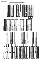
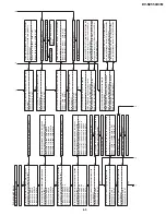
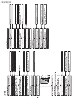
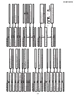
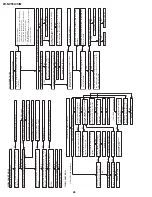
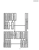
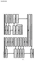
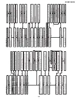
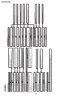
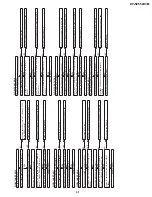
FLOW CHART NO.10
Set the disc on the disc tray.
Are the digital audio interface signals outputted
to the pins of main unit connector CN801?
CN801 3PIN AMCLK
CN801 4PIN ABCLK
CN801 5PIN ALRCLK
CN801 6PIN AOUT0
Check the main unit. (IC601 periphery circuit.)
Check the line between the pins of main unit
connector CN801 and the pins of IC6001.
CN801 3PIN
→
IC6001 5PIN AMCLK
CN801 4PIN
→
IC6001 3PIN ABCLK
CN801 5PIN
→
IC6001 1PIN ALRCLK
CN801 6PIN
→
IC6001 2PIN AOUT0
No
No
Yes
Yes
Yes
Sound do not oper
ate nor
mally
.
Are the digital audio interface signals inputted
to the pins of IC6001?
IC6001 5PIN AMCLK
IC6001 3PIN ABCLK
IC6001 1PIN ALRCLK
IC6001 2PIN AOUT0
Check the PC 3.3V line and PC 5V line.
Is 3.3V applied to the pin(7) and 5.5V applied to the
pins(10), (15) and (19) of the IC6001?
Are the audio interface signals outputted to the
pins of IC6001?
IC6001 16PIN L OUT
IC6001 13PIN R OUT
No
No
No
No
Check or replace IC6001.
Yes
Check the PC 9V line.
Is 9V applied to the pin(8) of IC6004?
No
Check or replace IC6004.
Yes
Are the system control interface signals outputted
to the pins of main unit connector CN801?
CN801 10PIN ADAC DA
CN801 11PIN ADAC CK
CN801 12PIN ADAC L
CN801 16PIN RSTO I
Check the main unit. (IC504 periphery circuit.)
Check the line between the pins of main unit
connector CN801 and the pins of IC6001.
CN801 10PIN
→
IC6001 26PIN ADAC DA
CN801 11PIN
→
IC6001 27PIN ADAC CK
CN801 12PIN
→
IC6001 28PIN ADAC L
CN801 16PIN
→
IC6001 22PIN RSTO I
No
No
Yes
Yes
Yes
Yes
Are the audio interface signals inputted to the
pins of IC6004?
IC6004 3PIN L OUT
IC6004 5PIN R OUT
Check the line between the pins of IC6001 and the
pins of IC6004.
IC6001 16PIN
→
IC6004 3PIN L OUT
IC6001 13PIN
→
IC6004 5PIN R OUT
Are the audio interface signals outputted to the
pins of IC6004?
IC6004 1PIN L OUT
IC6004 4PIN R OUT
Yes
Are the system control interface signals inputted
to the pins of IC6001?
IC6001 26PIN ADAC DA
IC6001 27PIN ADAC CK
IC6001 28PIN ADAC L
IC6001 22PIN RSTO I
*1
*2
*3
Check the DVD-H line and
Q6010.
No
Replace IC6010.
Yes
Is 9V applied to the pin(16) of IC6010?
Are the audio interface signals outputted to the
pins of IC6010?
IC6010 15PIN L OUT
IC6010 14PIN R OUT
No
No
Are the pins(9), (10) and (11) of IC6010 on "L" level?
Yes
Yes
Yes
Yes
Yes
No
Are the audio interface signals inputted to the pins
of IC6010?
IC6010 2PIN L OUT
IC6010 12PIN R OUT
Check the line between the pins of IC6001 and the
pins of IC6004 and the sound mute periphery
circuit.(Q6007-8.)
IC6004 1PIN
→
IC6010 2PIN L OUT
IC6004 4PIN
→
IC6010 12PIN R OUT
No
No
Are the audio interface signals inputted to the pins
of IC6011?
IC6011 3PIN L OUT
IC6011 5PIN R OUT
Check the line between the pins of IC6010 and the
pins of IC6011.
IC6010 15PIN
→
IC6011 3PIN L OUT
IC6010 14PIN
→
IC6011 5PIN R OUT
No
Is 9V applied to the pin(8) of IC6011?
Replace IC6011.
Yes
Are the audio interface signals outputted to the
pins of IC6011?
IC6011 1PIN L OUT
IC6011 7PIN R OUT
No
No
Are the audio signals output to the specific
outputted terminals?
Is the DVD audio signal (L) output to the
AUDIO OUT (L) terminal (J1202)?
Is the DVD audio signal (R) output to the
AUDIO OUT (R) terminal (J1202)?
Check the AUDIO OUT (L) terminal (J1202) and the
line between the pin(1) of IC6011 and the AUDIO
OUT (L) terminal (J1202).
Check the AUDIO OUT (R) terminal (J1202) and the
line between the pin(7) of IC6011 and the AUDIO
OUT (R) terminal (J1202).
No
No
Are the audio signals output to the specific
outputted terminals?
Is the DVD audio signal (L) output to the DVD
AUDIO OUT (L) terminal (J1204)?
Is the DVD audio signal (R) output to the DVD
AUDIO OUT (R) terminal (J1204)?
Check the DVDAUDIO OUT (L) terminal (J1204)
and the line between the pin(16) of IC6001 and the
DVD AUDIO OUT (L) terminal (J1204).
Check the DVDAUDIO OUT (R) terminal (J1204)
and the line between the pin(13) of IC6001 and the
DVD AUDIO OUT (R) terminal (J1204).
*1
*2
*3
Содержание DV-NC55C
Страница 75: ...75 DV NC55U C M M E M O ...
Страница 82: ...88 DV NC55U C M A B C D E F G H I J 1 2 3 4 5 6 7 8 9 10 13 3 VTR DISPLAY CIRCUIT SCHEMATIC DIAGRAM ...
Страница 91: ...103 DV NC55U C M 10 11 12 13 14 15 16 17 18 19 A B C D E F G H I J 1 2 3 4 5 6 7 8 9 10 Wiring Side SIDE A ...
Страница 93: ...105 DV NC55U C M 10 11 12 13 14 15 16 17 18 19 A B C D E F G H I J 1 2 3 4 5 6 7 8 9 10 Wiring Side SIDE B ...
Страница 98: ...110 DV NC55U C M A B C D E F G H I J 1 2 3 4 5 6 7 8 9 10 POWER PWB Component Side SIDE A Wiring Side SIDE A ...
Страница 100: ...112 DV NC55U C M A B C D E F G H I J 1 2 3 4 5 6 7 8 9 10 INTERFACE PWB Component Side SIDE A Wiring Side SIDE A ...
Страница 106: ...122 DV NC55U C M A B C D E F G H I J 1 2 3 4 5 6 7 8 9 10 M E M O ...
Страница 127: ...Ref No Part No Description Code Ref No Part No Description Code 143 DV NC55U C M ...

