


28
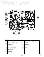
DV-NC55U/C/M
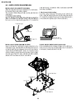
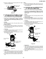
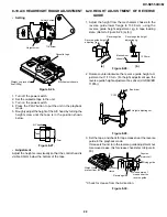
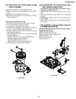
Figure 8-24.
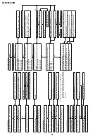
• Replacement
1. Solder the removed PWB to the new head assembly.
2. Adjust the height from the A/C head arm (lower surface)
to the A/C head plate to 10.8mm with slide calipers. (3
places of azimuth screw section, tilt screw section and A/
C head front section) (See the figure below.)
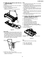
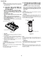
3. Align the left end of gear of A/C head arm with the
punched mark of chassis, tentatively tighten the screws
1
and
2
so as to ensure smooth motion of A/C head
arm. Tentative tightening torque must be 0.15 to 0.20
N·m (1.5 to 2.0kgf·cm).
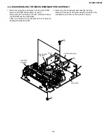
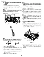
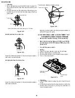
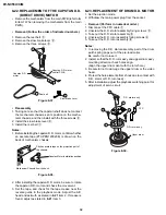
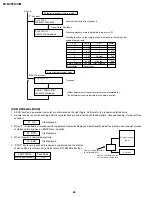
8-18. REPLACEMENT OF A/C (AUDIO/CONTROL)
HEAD
1. Remove the cassette housing control assembly.
2. In unloading state unplug the power cord.
•
Removal
1. Remove the screws
123
, Azimuth screw, Tilt screw.
2. Unsolder the PWB fitted to the A/C head.
Notes:
1. When replacing, never touch the head. If you touched,
clean with the cleaning liquid.
2. When removing the screw
3
, take care so that the
spring may out.
New A/C head ass'y
A/C head PWB
2
Spring
1
Solder
Never touch the head
10.8mm
10.8mm
Azimuth screw
Height screw
Tilt screw
A/C head plate
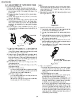
Figure 8-25.
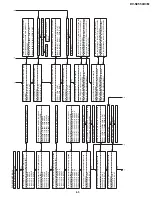
Note:
1. If the screws
1
and
2
are tighten tentatively too loose,
the azimuth and height of A/C head may change when
they are finally tightened. Therefore care must be taken.
2. After completion of A/C head be sure to adjust tape
running. (Execute the running adjustment by the method
described in 8-21.)
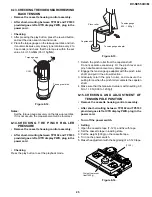
1
2
3
Height screw
Figure 8-23.
3
Left end of A/C head arm gear
Punched line mark on chassis
Tilt screw
Azimuth screw
Содержание DV-NC55C
Страница 75: ...75 DV NC55U C M M E M O ...
Страница 82: ...88 DV NC55U C M A B C D E F G H I J 1 2 3 4 5 6 7 8 9 10 13 3 VTR DISPLAY CIRCUIT SCHEMATIC DIAGRAM ...
Страница 91: ...103 DV NC55U C M 10 11 12 13 14 15 16 17 18 19 A B C D E F G H I J 1 2 3 4 5 6 7 8 9 10 Wiring Side SIDE A ...
Страница 93: ...105 DV NC55U C M 10 11 12 13 14 15 16 17 18 19 A B C D E F G H I J 1 2 3 4 5 6 7 8 9 10 Wiring Side SIDE B ...
Страница 98: ...110 DV NC55U C M A B C D E F G H I J 1 2 3 4 5 6 7 8 9 10 POWER PWB Component Side SIDE A Wiring Side SIDE A ...
Страница 100: ...112 DV NC55U C M A B C D E F G H I J 1 2 3 4 5 6 7 8 9 10 INTERFACE PWB Component Side SIDE A Wiring Side SIDE A ...
Страница 106: ...122 DV NC55U C M A B C D E F G H I J 1 2 3 4 5 6 7 8 9 10 M E M O ...
Страница 127: ...Ref No Part No Description Code Ref No Part No Description Code 143 DV NC55U C M ...