


11
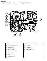
DV-NC55U/C/M
26
25
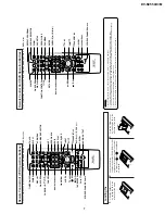
Connector
28
31
29
30
32
32
34
33
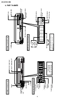
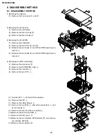
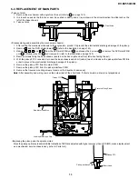
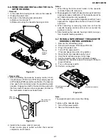
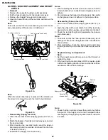
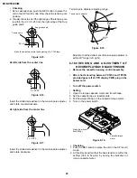
(14)Remove the connector.
(15)Remove the three screws
g
and
h
.
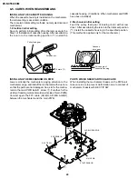
5) Removing the cassette housing control/VTR mechanism.
(1) Remove the two screws
k
.
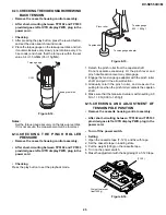
(2) Remove the two screws
l
.
(3) Remove the one screw
;
.
(4) Remove the H/A shield case (upper)
.
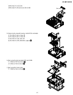
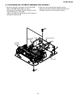
6) Removing the terminal plate/VTR main PWB.
(1) Remove the four screws
.
(2) Remove the one screw
.
7) Removing the bottom plate.
(1) Remove the six screws
.
31
32
33
34
Содержание DV-NC55C
Страница 75: ...75 DV NC55U C M M E M O ...
Страница 82: ...88 DV NC55U C M A B C D E F G H I J 1 2 3 4 5 6 7 8 9 10 13 3 VTR DISPLAY CIRCUIT SCHEMATIC DIAGRAM ...
Страница 91: ...103 DV NC55U C M 10 11 12 13 14 15 16 17 18 19 A B C D E F G H I J 1 2 3 4 5 6 7 8 9 10 Wiring Side SIDE A ...
Страница 93: ...105 DV NC55U C M 10 11 12 13 14 15 16 17 18 19 A B C D E F G H I J 1 2 3 4 5 6 7 8 9 10 Wiring Side SIDE B ...
Страница 98: ...110 DV NC55U C M A B C D E F G H I J 1 2 3 4 5 6 7 8 9 10 POWER PWB Component Side SIDE A Wiring Side SIDE A ...
Страница 100: ...112 DV NC55U C M A B C D E F G H I J 1 2 3 4 5 6 7 8 9 10 INTERFACE PWB Component Side SIDE A Wiring Side SIDE A ...
Страница 106: ...122 DV NC55U C M A B C D E F G H I J 1 2 3 4 5 6 7 8 9 10 M E M O ...
Страница 127: ...Ref No Part No Description Code Ref No Part No Description Code 143 DV NC55U C M ...


