AR-6020V OPERATIONAL DESCRIPTIONS 11 – 7
B.Operational descriptions
(1)General
This section performs the following operations.
1) Light is radiated onto the document by the scanner lamp and
the reflected image is scanned by the 4-line (RGB+BW) CCD
elements to be converted into analog image signals.
2) The analog image signals are converted into 10-bit digital sig-
nals by the A/D converter.
3) The digital image signals are sent to the MCU PWB for image
processing.
(2)Detailed descriptions
a. Optical section drive
The optical section is driven as follows: The drive power is transmit-
ted from the scanner motor (MIRM) through the belt to the drive
pulley/wire, and the copy lamp unit and the mirror base which are
attached to the wire are driven.
The scanner motor (MIRM) is controlled with the signals sent from
the MCU PWB.
b. Scanner lamp drive
The scanner lamp is driven by the scanner lamp drive voltage
which is generated by the LED drive PWB with the control signals
sent from the MCU PWB.
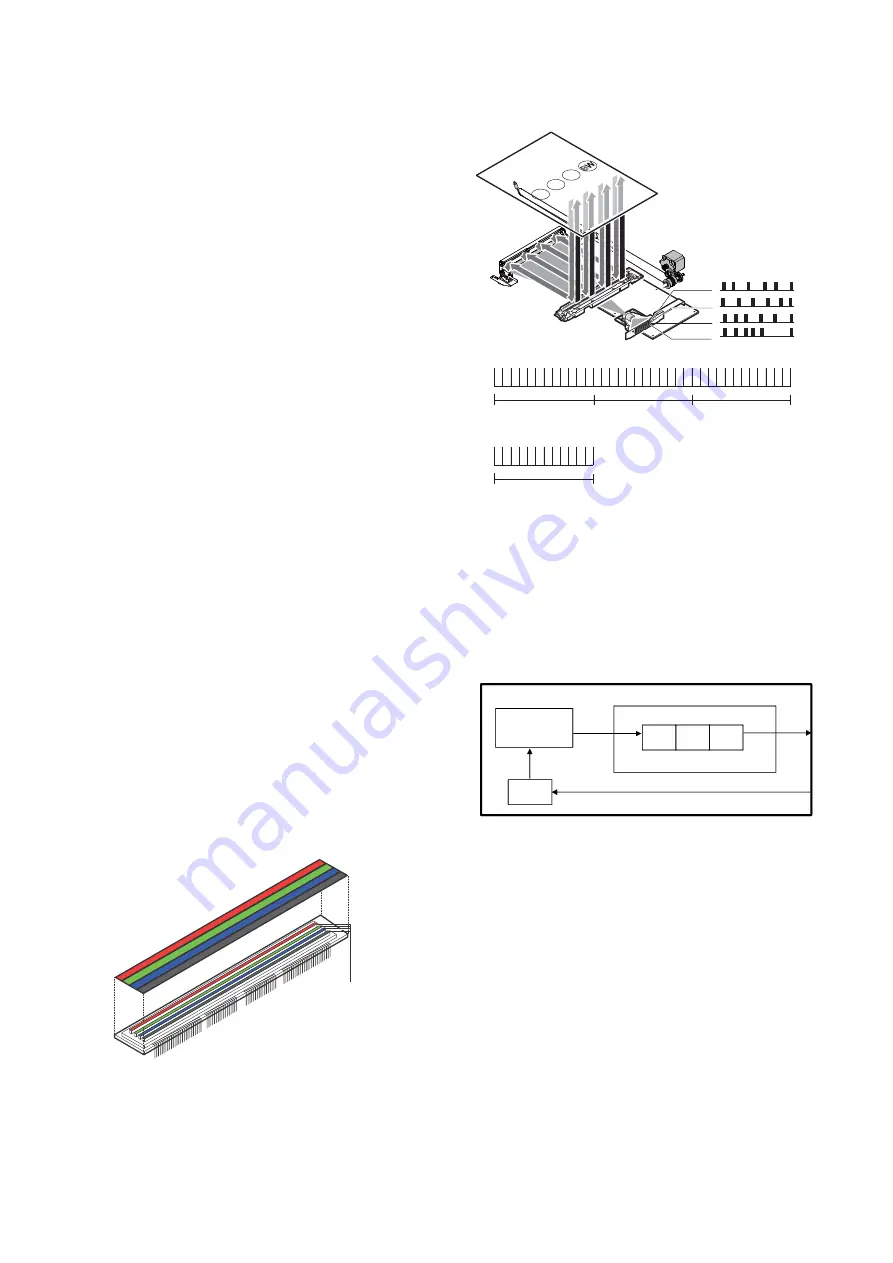
c. Image scan and color separation
Light is radiated onto the document by the scanner lamp and the
reflected image is scanned by the 4-line (RGB+BW) CCD elements
to be converted into analog image signals.
The color components are extracted into R, G, B and BW by the
three kinds of CCD elements (R, G, B and BW).
The red CCD extracts the red component of an image, the green
CCD extracts the green component, the blue CCD extracts the blue
component, the BW CCD extracts the BW component. This opera-
tion is called color separation.
The CCD element is apparently seen as one unit, but it includes the
four kinds of elements (R, G, B and BW).
The CCD element scans the document in the main scanning direc-
tion. Scanning in the sub scanning direction is made by shifting the
scanner unit with the scanner motor.
The document images are optically reduced by the lens and
reflected to the CCD.
The scanning direction is 400dpi.
d. Image signal A/D conversion
1) Each image signal (analog) of R, G, B and BW is converted into
a 10bit digital signal by the A/D converter in the CCD PWB.
Each color pixel has 10bit information.
2) Each 10bit digital image signal of R, G, B and BW is outputted
from the CCD PWB and sent to the MCU PWB, where it is con-
verted into an 8bit signal.
e. Zooming operation
Zooming in the sub scanning direction is performed by changing
the scanning speed in the sub scanning direction.
Zooming in the main scanning direction is not made optically, but
performed by the image process technology (software).
##$ %LEMENTS
,).%3 ##$ 5.)4
R,G,B,BW Color filter
B
R
G
R
G
B
BW
BW
(Image data for 1 line)
BW
Black/White
component image data
B
Red component
image data
Green component
image data
Blue component
image data
R
G
Analog IC
CCD
䠄
3Line-OutPut
䠅
CDS PGA
ADC
Buffer
R
G
B
B/W
CCD PWB


