Assembly
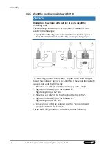
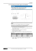
9. Tighten screw (4) while pressing the control cam in the
direction of the gripper fingers.
IMPORTANT! The control cam
may tilt in the guide if it has not been tightened properly.
✓
Switching point is set.
10. Bring product into the "Gripper open" or "Part gripped"
position and test the function.
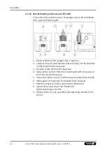
Position "Gripper closed" or "Part gripped (O.D. gripping)"
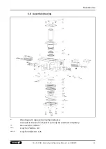
1. Loosen screw (4) and remove the contol cam (6) for inductive
sensing from the base jaw.
2. Push the control cam (6) from the mounting kit into the base
jaw.
✓
Make sure that the side with the magnet is facing outwards.
3. Tighten screw (4) slightly
4. Slide the sensor 1 (1) into the bracket (2) until it stops.
5. Tighten the screw (3) on the bracket (2).
Tightening torque: 0.2 Nm
6. Close gripper or grip part.
7. Unfasten the screw (4).
8. Turn the screw (5) to adjust the position of the control cam (6).
✓
Slide control cam (6) outwards until the sensor 2 (1) no
longer responds.
Move the control cam (6) back towards the inside until the
sensor 1 (1) begins to switch.
9. Tighten screw (4) while pressing the control cam in the
direction of the gripper fingers.
IMPORTANT! The control cam
may tilt in the guide if it has not been tightened properly.
✓
Switching point is set.
10. Bring product into the "Gripper closed" or "Part gripped"
position and test the function.
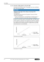
NOTE
If the switching position cannot be queried, it may be that the
alignment of the control cam has to be changed,
.
37
13.00 | PGB | Assembly and Operating Manual | en | 389275
Содержание PGB
Страница 1: ...Original operating manual Assembly and Operating Manual PGB 2 finger parallel gripper with center bore...
Страница 50: ......
Страница 51: ......


