background image

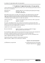
Translation of original declaration of incorporation

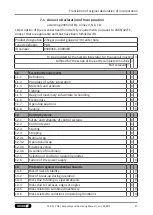
7.1 Annex to Declaration of Incorporation

according 2006/42/EG, Annex II, No. 1 B

1.Description of the essential health and safety requirements pursuant to 2006/42/EC,
Annex I that are applicable and that have been fulfilled with:

Product designation 2-finger parallel gripper with center bore
Type designation

PGB

ID number

0300360...0300369

To be provided by the System Integrator for the overall machine

Fulfilled for the scope of the partly completed machine

Not relevant

1.1

Essential Requirements

1.1.1

Definitions

X

1.1.2

Principles of safety integration

X

1.1.3

Materials and products

X

1.1.4

Lighting

X

1.1.5

Design of machinery to facilitate its handling

X

1.1.6

Ergonomics

X

1.1.7

Operating positions

X

1.1.8

Seating

X

1.2

Control Systems

1.2.1

Safety and reliability of control systems

X

1.2.2

Control devices

X

1.2.3

Starting

X

1.2.4

Stopping

X

1.2.4.1

Normal stop

X

1.2.4.2

Operational stop

X

1.2.4.3

Emergency stop

X

1.2.4.4

Assembly of machinery

X

1.2.5

Selection of control or operating modes

X

1.2.6

Failure of the power supply

X

1.3

Protection against mechanical hazards

1.3.1

Risk of loss of stability

X

1.3.2

Risk of break-up during operation

X

1.3.3

Risks due to falling or ejected objects

X

1.3.4

Risks due to surfaces, edges or angles

X

1.3.5

Risks related to combined machinery

X

1.3.6

Risks related to variations in operating conditions

X

47

13.00 | PGB | Assembly and Operating Manual | en | 389275

Содержание PGB

Страница 1: ...Original operating manual Assembly and Operating Manual PGB 2 finger parallel gripper with center bore...

Страница 2: ...n 13 00 09 08 2022 en Dear Customer thank you for trusting our products and our family owned company the leading technology supplier of robots and production machines Our team is always available to a...

Страница 3: ...13 2 12 1 Protection during handling and assembly 13 2 12 2 Protection during commissioning and operation 14 2 12 3 Protection against dangerous movements 14 2 12 4 Protection against electric shock 1...

Страница 4: ...is not executing the complete stroke 40 5 3 Product opens or closes abruptly 40 5 4 Gripping force is dropping 41 5 5 Product does not achieve the opening and closing times 41 6 Maintenance 42 6 1 No...

Страница 5: ...ents listed under 1 1 3 6 are applicable NOTE The illustrations in this manual are intended to provide a basic understanding and may deviate from the actual version 1 1 1 Presentation of Warning Label...

Страница 6: ...the accessories The documents labeled with an asterisk can be downloaded from schunk com 1 2 Warranty If the product is used as intended the warranty is valid for 36 months from the ex works delivery...

Страница 7: ...Magnetic switch RMS Programmable magnetic switch MMS P Position monitoring FPS Position monitoring APS Exact type designation of the compatible sensors see catalog Information on handling sensors is a...

Страница 8: ...e protective measures are taken against outdoor exposure The product is not suitable for use in salty air The product can be used within the permissible load limits and technical data for holding work...

Страница 9: ...ake sure that the product and the top jaws are a sufficient size for the application 2 5 Ambient conditions and operating conditions Required ambient conditions and operating conditions Incorrect ambi...

Страница 10: ...lated to the product Trained electrician Due to their technical training knowledge and experience trained electricians are able to work on electrical systems recognize and avoid possible dangers and k...

Страница 11: ...ting protective clothing and also wear long hair in a hairnet when dealing with moving components 2 8 Notes on safe operation Incorrect handling of the personnel Incorrect handling and assembly may im...

Страница 12: ...r in case of malfunctions Immediately remove the product from operation and report the malfunction to the responsible departments persons Order appropriately trained personnel to rectify the malfuncti...

Страница 13: ...and assembly Incorrect handling and assembly Incorrect handling and assembly may impair the product s safety and cause serious injuries and considerable material damage Have all work carried out by a...

Страница 14: ...avert danger Until the installed monitors become effective it must be assumed that the drive movement is faulty with its action being dependent on the control unit and the current operating condition...

Страница 15: ...that all components and assembly groups are included in the local potential equalisation in accordance with the applicable regulations While paying attention to the actual conditions of the working e...

Страница 16: ...ble protective equipment WARNING Risk of injury from objects falling and being ejected Falling and ejected objects during operation can lead to serious injury or death Take appropriate protective meas...

Страница 17: ...Parts are under spring tension on products which clamp using spring force or which have gripping force maintenance While disassembling components can move unexpectedly and cause serious injuries Disa...

Страница 18: ...ium Compressed air compressed air quality according to ISO 8573 1 7 4 4 Nominal working pressure bar 6 Min pressure bar 2 5 Max pressure bar 8 0 Pressure range for air purge bar 0 5 1 Noise emission d...

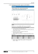
Страница 19: ...uries Before starting any work on the product Switch off the power supply and secure against restarting Make sure that no residual energy remains in the system Evenness of the mounting surface The val...

Страница 20: ...and max depth of engagement for rear mounting M5 12 M5 15 M6 14 M8 20 4 Thread diameter with gripper fastening from the front M4 M4 M5 M6 5 Thread diameter with gripper fastening at the side M4 M5 M6...

Страница 21: ...s recommended in this case in order to maintain the dynamic effect for some time Product variants are also offered with mechanical gripping force via springs which also ensure a minimum clamping force...

Страница 22: ...e 64 80 100 125 1 Thread diameter of the air connections A open B close M5 M5 G 1 8 G 1 8 2 Thread diameter air purge connection S M5 M5 M5 M5 3 Thread diameter Hose free direct connection at the base...

Страница 23: ...eet and 4 2 1 23 For technical data for the suitable sensors see assembly and operating manual and catalog datasheet The assembly and operating manual and catalog datasheet are included in the scope o...

Страница 24: ...o the screw 2 2 Remove control cam 1 from the product turn and re insert it into the product 3 Turn the screw 3 to push the position of the control cam 1 4 2 3 Switch off hysteresis for magnetic switc...

Страница 25: ...29 9 125 22 9 31 8 Dimen sion l1 Bottom edge of the product to double arrow of the sensor Dimen sion l2 Bottom edge of the product to front edge of the sensor NOTE The magnetic switch MMS 22 PI1 can...

Страница 26: ...the housing of the gripper The switching point of the position Gripper open and Gripper closed have already been set by SCHUNK If these positions are to be used carry out the following 1 Slide the sen...

Страница 27: ...the function Position Gripper closed or Part gripped O D gripping 1 Slide the sensor 2 1 into the bracket 2 until it stops 2 Tighten the screw 3 on the bracket 2 Tightening torque 0 2 Nm 3 Close grip...

Страница 28: ...the sensor 1 1 back again slowly until it switches 5 Secure the sensor 1 1 using the set screw 4 Tightening torque 10 Ncm 6 Bring product into the Gripper open or Part gripped position and test the f...

Страница 29: ...t available slide the sensor according to dimension I1 into the groove 2 4 2 4 25 1 Turn the sensor 1 into the groove 2 OR Slide the sensor 1 into the groove 2 until the sensor 1 stops at the T nut 3...

Страница 30: ...he maximal tightening torque NOTE If there is no T nut available slide the sensor according to dimension I1 into the groove 2 4 2 4 25 1 Turn the sensor 1 into the groove 2 OR Slide the sensor 1 into...

Страница 31: ...timal position in the groove itself SCHUNK recommends Optimal Mode for setting the sensors Setting the sensor in Optimum mode 1 Put product in the position in which it is to be set 2 Hold teaching too...

Страница 32: ...the groove 2 OR Slide the sensor 1 1 into the groove 2 until the sensor 1 1 stops at the T nut 3 2 Secure the sensor 1 1 using the set screw 4 Tightening torque 10 Ncm 3 Adjust sensor 1 1 see sensor...

Страница 33: ...following table 1 Turn the sensor 1 into the groove 2 OR Slide the sensor 1 into the groove 2 until the sensor 1 stops at the T nut 3 2 Secure the sensor 1 using the set screw 4 Tightening torque 10 N...

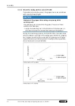
Страница 34: ...pply the switching cam in the direction of the base jaw so that the cam does not contact the housing of the gripper During the monitoring process the first 8 of the nominal stroke will not produce a c...

Страница 35: ...ends the adhesive Loctite 290 or 638 5 Slide control cam 6 into the base jaw to the stop Ensure that the higher front side of the control cam 6 is pointing outwards 6 IMPORTANT The control cam 6 must...

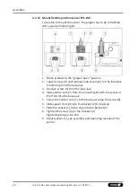
Страница 36: ...Position Gripper open or Part gripped I D gripping 1 Loosen screw 4 and remove the contol cam 6 for inductive sensing from the base jaw 2 Push the control cam 6 from the mounting kit into the base jaw...

Страница 37: ...cket 2 until it stops 5 Tighten the screw 3 on the bracket 2 Tightening torque 0 2 Nm 6 Close gripper or grip part 7 Unfasten the screw 4 8 Turn the screw 5 to adjust the position of the control cam 6...

Страница 38: ...ol cam 6 for the inductive monitoring from the base jaw 3 Remove screw 5 from the base jaw 4 Slide control cam 7 from the mounting kit with the recess at the front into the base jaw 5 Screw the contro...

Страница 39: ...e top and sides of the control cam 6 from the mounting kit Make sure that there is no adhesive on the bottom of the control cam 6 which comes into contact with the sensor SCHUNK recommends the adhesiv...

Страница 40: ...ot executing the complete stroke Possible cause Corrective action Dirt deposits between cover and piston Clean and if necessary re lubricate Dirt deposits between basic jaws and guidance Disassemble a...

Страница 41: ...s occurs without bouncing and hitting Check compressed air lines Inner diameters of compressed air lines are of sufficient size in relation to compressed air consumption Flow rate of valve is sufficie...

Страница 42: ...hardening lubricants Lubricants harden more quickly at temperatures above 60 C leading to possible product damage Reduce the lubricant intervals accordingly Interval Mio cycles 1 6 3 Lubricants Lubric...

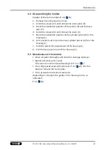
Страница 43: ...t 13 and remove cylinder piston 6 from the housing 1 7 Push the piston 3 upwards out of the housing 1 8 Pull the base jaws 2 out of the housing 1 6 5 Maintenance of the module Clean all parts thorough...

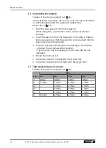
Страница 44: ...he base jaws 2 so that the piston 3 can be pushed into the base jaws 2 with no problem 3 Push the cylinder piston 6 into the housing 1 from below Observe the correct assembly position Pay attention th...

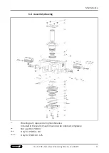
Страница 45: ...drawing Wearing part replace during maintenance Included in the seal kit Seal kit can only be ordered completely Not used for PGB 64 Only for PGB 64 80 Only for PGB 100 125 45 13 00 PGB Assembly and O...

Страница 46: ...r parallel gripper with center bore PGB pneumatic ID number 0300360 0300369 The partly completed machine may not be put into operation until conformity of the machine into which the partly completed m...

Страница 47: ...roducts X 1 1 4 Lighting X 1 1 5 Design of machinery to facilitate its handling X 1 1 6 Ergonomics X 1 1 7 Operating positions X 1 1 8 Seating X 1 2 Control Systems 1 2 1 Safety and reliability of con...

Страница 48: ...ustable guards restricting access X 1 4 3 Special requirements for protective devices X 1 5 Risks due to other hazards 1 5 1 Electricity supply X 1 5 2 Static electricity X 1 5 3 Energy supply other t...

Страница 49: ...2 1 Foodstuffs machinery and machinery for cosmetics or pharmaceutical products X 2 2 Portable hand held and or guided machinery X 2 2 1 Portable fixing and other impact machinery X 2 3 Machinery for...

Страница 50: ......

Страница 51: ......

Страница 52: ...ping and gripping technology Bahnhofstr 106 134 D 74348 Lauffen Neckar Tel 49 7133 103 0 Fax 49 7133 103 2399 info de schunk com schunk com Folgen Sie uns I Follow us 08 2022 2022 SCHUNK GmbH Co KG 13...

Отзывы: