Assembly
06.00 | NSR-A | Assembly and Operating Manual | en | 389722
35
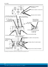
Overview of assembly
Ø
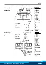
Connect the pallet changing system in accordance with pneumatic
circuit diagram,
Pneumatic circuit diagram NSR-A 100
45] or
Pneumatic circuit diagram NSR-A 160
46].
✓
Seal air connections not required using the locking screws
from the accessory pack.
✓
Screw on air connections.
Ø
Screw changeover head with the robot flange.
Ø
Screw clamping pin into the pallet adapter.
Ø
Tighten pallet adapter with the customer's clamping pallet.
Ø
Observe tightening torques for the mounting screws,
47].
Ø
Installing the sensors,
51].
Ø
Test function of the pallet changing system and connect and
disconnect transport load,
Connection and disconnection of transport loads
NOTE
• Only mount original SCHUNK clamping pins on the pallet
adapter with the prescribed mounting screw. Observe the
tightening torque. Clamping pins are available from SCHUNK as
a spare part.
• Check the screw fitting of the clamping pin at regular intervals
to ensure that it is secure.
• For customer-specific pallet adapters produced by the
customer, full support at the flat surface of the changeover
head must be guaranteed,
conditions for clamping pins in customer-specific pallet
adapters
The hoses and cables required for the energy supply for the
pallet changing system must be laid and protected suitably on
the pallet handling.
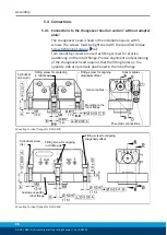
For more information and drawings on the connections, see the
next chapter entitled "Connections" ,
36].
Содержание NSR-A 100
Страница 1: ...Translation of Original Operating Manual Assembly and Operating Manual NSR A Pallet Changing System ...
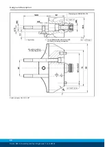
Страница 62: ...Maintenance 62 06 00 NSR A Assembly and Operating Manual en 389722 7 4 2 Assembly drawings NSR A 160 ...
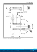
Страница 63: ...Maintenance 06 00 NSR A Assembly and Operating Manual en 389722 63 Without adapter plate ...


