13
C
OMMUNICATION
C
OMMUNICATION PORTS
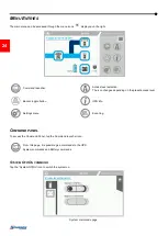
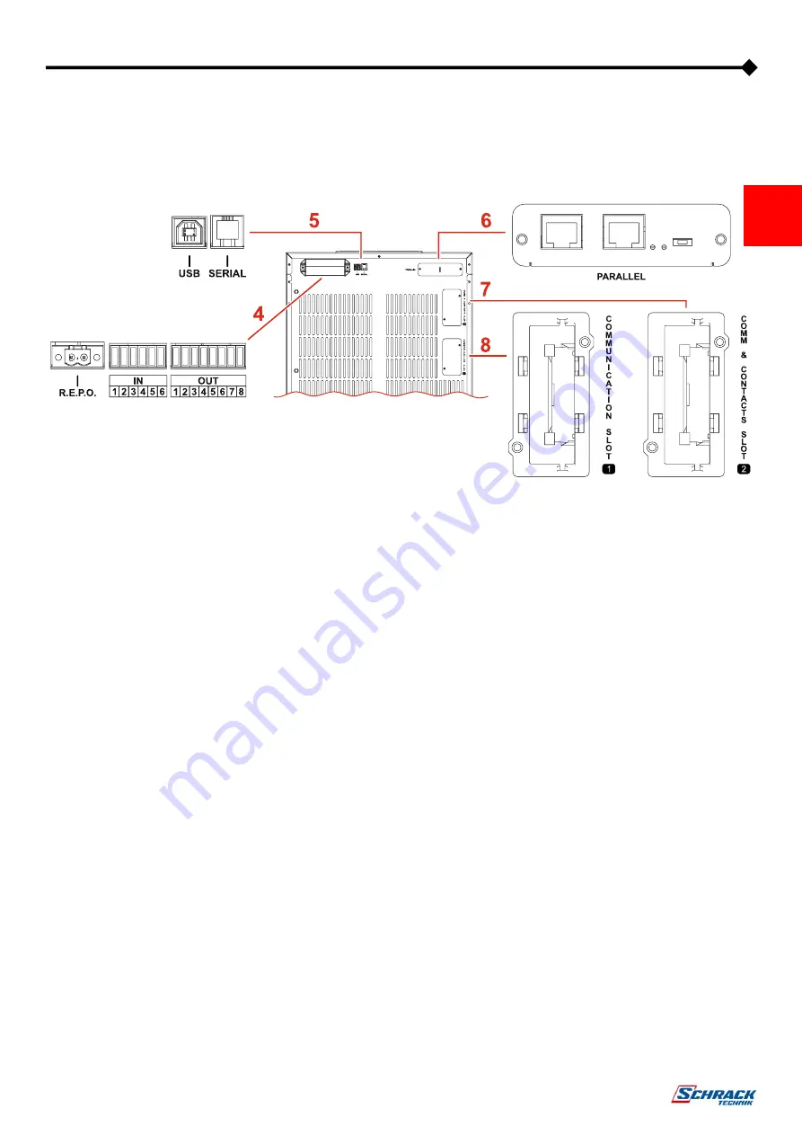
The communication ports are situated in the top section at the rear of the UPS. Refer to the following image for the exact location of
each port.
4
R.E.P.O / IN / OUT:
these are digital inputs and dry contact outputs
available to the user to perform various functions.
The R.E.P.O. input is fixed for the Remote
Emergency Power Off normally closed contact (the
UPS is supplied with a link pre-fitted from the factory
as standard).
All the other inputs and outputs can be programmed
with the aid of the configuration software.
Please refer to the installation manual for more
information with regards to the connections.
5
USB / Serial RS232 ports:
These ports allow the UPS to communicate with a
computer enabling the system to be monitored and
configured.
The two ports cannot be used simultaneously.
The USB port is to be used as an alternative to the
RS232 serial interface.
USB port function is only guaranteed when using a
cable no longer than 1.5m. If a longer cable is
required, the use of the RS232 serial interface is
recommended.
6
Parallel board:
An optional parallel board can be fitted into the UPS
in order to enable up to eight three phase units
(USS3T) or four single phase units (USS3M) to be
connected in parallel.
For further information with regards to this function,
please refer to the parallel board kit user manual.
7
SLOT 2 - Communication and contact Slot:
Slot to accommodate additional communication
cards (default configuration), or contacts/relay
expansion cards.
For further information with regards to the
communications expansion cards, please refer to
the communications card user manual.
8
SLOT 1 - Communication Slot:
Slot to accommodate the additional communication
cards (no contacts/relay card).
For further information with regards to the
communications cards, please refer to the
communications card user manual.


