


48
OPTIONS
E
XTERNAL BATTERY CABINET
All the UPS within the USS3T - USS3M family can be supplied with matching external Battery Cabinets. These can be supplied by the
factory or by a local supplier subject to being compliant with the statement below.
Read the Battery Cabinet manual before connecting the batteries.
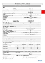
The Battery Cabinet total voltage shall meet the requirements of the UPS (refer to the Battery Cabinet nameplate
and/or Battery Cabinet User Manual).
THE CONNECTION BETWEEN THE UPS AND THE BATTERY CABINET MUST BE MADE WITH THE UPS
POWERED OFF AND ISOLATED FROM THE INCOMING MAINS SUPPLY
UPS POWER-OFF PROCEDURE:
Please Refer to the “Operative Procedures”, “System off command” paragraph.
Open all of the isolation switches and fuse holders present within the UPS.
Isolate the UPS from the incoming mains supply network by opening all the external protective devices situated on the input
and output lines.
Wait a few minutes before proceeding to work on the UPS.
Remove the terminal cover from the UPS.
CONNECTING THE BATTERY CABINET:
ATTENTION: For the cross sectional area of the connection cables please refer to the “Installation Manual”,
”POWER CONNECTION INFORMATION” paragraph. Furthermore, the three battery cables (+, -, N) must be placed
close to each other in order to avoid loops.
For EMI reasons, if possible, place the UPS and Battery Cabinet side by side in order to keep the cable length as
short as possible (suggested 3mt maximum). If it is not possible due to space limitations, maximum admitted
length is 25mt. If extended length is required, please contact your local service centre.
Check that the battery voltage of the Battery Cabinet corresponds to that allowed by the UPS (check the data plate on the
Battery Cabinet and the UPS manual)
IMPORTANT:
make sure that the fuse holders of the UPS and the Battery Cabinet are open.
Remove the terminal cover from the Battery Cabinet.
Connect the earthing terminals of the UPS and Battery Cabinet using a yellow/green wire of the proper cross section.
Connect the wires to the terminals of the UPS and the Battery Cabinet:
- terminals marked with the
+
symbol with the red cable (or colour as stipulated by local/country regulations)
- terminals marked with the
N
symbol with the blue cable (or colour as stipulated by local/country regulations)
- terminals marked with the
–
symbol with the black cable (or colour as stipulated by local/country regulations)
The correspondence indicated by the symbols printed on the terminal cover of the Battery Cabinet and the UPS must be
respected.
Please refer to the Installation manual for further information with regards to the wiring cross sectional area.
Replace all of the terminal covers previously removed.


