15
B
ATTERY WORKING
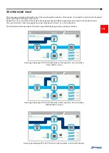
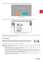
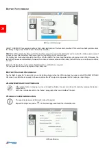
When the UPS is supplying the output with the batteries present, if the mains supply network falls outside the pre-set tolerances, for
example in case of a blackout, voltage or frequency disturbance, the system automatically switches to BATTERY OPERATING
STATUS and draws power from the batteries to support the load.
Once the mains supply network is again clean and stable, the system automatically returns back to the pre-set operational mode.
T
EMPORARY BYPASS
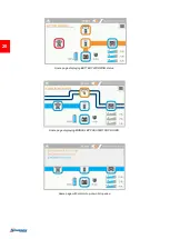
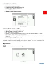
During this operational state, the load is directly powered by the incoming mains supply, therefore, any input disturbances will
directly affect the connected load.
M
ANUAL BYPASS
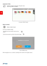
The manual bypass enables the user to physically connect the UPS input directly to the output. This condition is required to perform
maintenance operations on the UPS without the need to disconnect the power from the protected load.
Before closing the manual bypass switch, an auxiliary contact informs the UPS that the load is going to be transferred to man ual
bypass. This activates an immediate, synchronised transition to the internal static bypass to ensure a safe closure of the manual
bypass power contacts.
WARNING: Maintenance work inside the UPS is to be performed exclusively by qualified staff. There may be
voltages present within the UPS even when the input, output and battery fuse holders are open. Removal of the
UPS panels by non-qualified staff may result in injury to the operator and damage the equipment.
For further instructions in relation to the manual bypass functi
on, please refer to the “Switching the system to manual bypass” chapter.
O
THER
F
EATURES
B
ACK
-
FEED PROTECTION
The UPS has an internal protection against back-feed. This protection acts by means of a sensing circuit which turns off the inverter
if a fault within the static switch is detected. In this condition, to avoid interrupting the supply to the connected load, the UPS switches
to bypass line.
If the bypass is not available, the connected load is switched off.
To avoid stopping the inverter, a dry contact can be configured to drive a disconnection device. This device must be installed upstream
of the bypass input to the UPS, in this case when a back-feed fault occurs, the system opens the external disconnection device (for
further information, refer to the configuration software manual).
The label supplied with the UPS must be affixed to all isolators installed in the electrical system upstream of the
UPS.
L
ATCH
-
ON
-
BYPASS FUNCTION
The UPS has an internal device (redundant bypass power supply) which activates the bypass automatically when a major failure
occurs within the UPS; thus, keeping the load powered without any internal protection and without any limitation to the power supplied
to the load.
WARNING:
Under these emergency conditions, any disturbance present at the input supply will affect the load.
P
OWER
W
ALK
-I
N
The Power Walk-In function can be activated through the configuration software. This function enables, upon reconnection to the
network (following a mains supply failure), a progressive absorption of power from the incoming supply, in order to avoid stressing
(due to the inrush current) a generator or a weak network which is potentially installed upstream. The duration of the Power Walk-In
mode can be set between 1 to 120 seconds. As default configuration the Power Walk-In is disabled, however the maximum input
current is limited. During this mode the required power is partially taken from the batteries and partially from the network whilst
maintaining a sinusoidal power ramp-up. The battery charger is only switched on once the transition is complete.


