12 Troubleshooting
Operating Manual 90° ACTUSAFE CMF(S)QT
OM-ENGLISH-Failsafe-QT-16xx-V2.00-2022.03.01
the manufacturer of the equipment or through cable entries of comparable quality as well as the same ex- or IP protection
class.
If screws need to be replaced, it is preferable to use original replacement parts. The tensile strength of the screws must be
at least 400 N/mm
2
!
12
Troubleshooting
Upon warning or error, the bottom line of the display will show the corresponding plain text description. This event will also
be entered into the history (see section 8.2, page 71).
12.1
History Entries
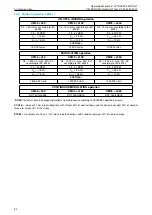
Listed below are all possible history entries. In case of a warning, the alarm will be visualized on the left side of the main
display. If an alarm occurs, the display background light will be red, and the main display will show, that the actuator is not
ready.
NOTE:
Each error has a unique error number. Each error also has its separate “OK” message in the history after the
fault has gone.
History Entry
Type
Description
#3: Mot. temp. warn.
#19: Mot. temp. warn. OK
Warning
The motor temperature is in the critical range
although the actuator remains fully functional.
#4: Mot. temp. switchoff
#20: Mot. temp. switchoff OK
Alarm
Overtemp in motor, fault on Basis or BLDC, On Basis:
loss of main power (3x400V) or cable break between
CSC and motor; on BLDC: cable break between
BLDC and motor.
#5: Phase sequ. fault
#6: Phase sequ. OK
n.a.
Cause on Basis: Active phase sequence detection on
single phase actuators, loss of main power while
connected to external 24 VDC auxiliary voltage, or
loss of phase L2.
#7: Ready
Information
Written to the history after all errors are gone.
#8: Power On
Information
Is written to the history after power on the actuator,
even if there are some errors.
#9: Power supply Fault
#21: Power supply OK
Alarm
No power supply to the power electronics (when the
controller is powered from the auxiliary power input).
Defect of power electronics – please contact the
manufacturer.
#11: Failsafe Fault
#12: Failsafe OK
Alarm
Communication error between Failsafe board and
Logic, loss of external 24 V Failsafe Voltage, or
overtemp. on Failsafe brake.
#13: Manual override
#14: Manual override Off
Alarm
Manual override on Failsafe active (visible in status
S4), cable/switch broken.
#17: Travel Sensor Fault
#18: Travel Sensor OK
Alarm
The travel unit is outside the permitted range
(potentiometer fault on Basis), cable broken, or
multiturnsensor calibration lost on CM – please
contact the manufacturer.
#22: Torque Sensor Fault
#23: Torque Sensor OK
n.a.
Potentiometer fault on Basis, or cable broken.
#24: Bus Fault
#25: Bus OK
Warning
No communication with the optional bus system.
#26: Bus Watchdog
#27: Bus Watchdog OK
Warning
Watchdog for bus communication has reacted.
#28: Undervoltage> Warning
#29: Voltage OK
Warning
The input voltage is below the regular voltage range,
but motor operation is still possible.
#32: Internal Comm. Fault L>Error
#33 Internal Comm. Fault L>OK
Alarm
Communication error between Logik and
Basis/BLDC, cable broken between boards, or board
defect.
#34: Internal Comm. Fault D>Error
#35: Internal Comm. Fault D>OK
Alarm
Communication error between Display and Logik,
cable broken between boards, boards defect, or
firmware update on Logik not properly done.
continued on next page
76
Содержание CM03
Страница 1: ...Operating Manual 90 ACTUSAFE CMF S QT OM ENGLISH Failsafe QT 16xx V2 00 2022 03 01 ...
Страница 97: ...CM03 FSQT ...
Страница 98: ...CM06 FSQT ...


