background image

CONTENTS

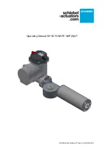
Operating Manual 90° ACTUSAFE CMF(S)QT

OM-ENGLISH-Failsafe-QT-16xx-V2.00-2022.03.01

Contents

Contents

2

Operating Manual 90° Actusafe CMF(S)QT

3

Manual for 90-Degree Failsafe-Actuators - CMF(S)QT

3

1

Safety instructions . . . . . . . . . . . . . . . . . . . . . . . . . . . . . . . . . . . . . . . . . . . . . . . . . . . . . . . . . . . .

3

2

Introduction. . . . . . . . . . . . . . . . . . . . . . . . . . . . . . . . . . . . . . . . . . . . . . . . . . . . . . . . . . . . . . . . .

4

3

Functional Description of the CMF(S)QT - Failsafe Drive . . . . . . . . . . . . . . . . . . . . . . . . . . . . . . . . . .

5

3.1

Failsafe-direction . . . . . . . . . . . . . . . . . . . . . . . . . . . . . . . . . . . . . . . . . . . . . . . . . . . . . . . . .

6

3.2

Moving-behaviour of the actuator . . . . . . . . . . . . . . . . . . . . . . . . . . . . . . . . . . . . . . . . . . . . . . .

7

3.2.1

Moving behaviour electrical mode. . . . . . . . . . . . . . . . . . . . . . . . . . . . . . . . . . . . . . . . . .

7

3.2.2

Moving behaviour failesafe mode . . . . . . . . . . . . . . . . . . . . . . . . . . . . . . . . . . . . . . . . . .

7

4

General Information . . . . . . . . . . . . . . . . . . . . . . . . . . . . . . . . . . . . . . . . . . . . . . . . . . . . . . . . . . .

7

4.1

Serial number . . . . . . . . . . . . . . . . . . . . . . . . . . . . . . . . . . . . . . . . . . . . . . . . . . . . . . . . . . .

7

4.2

Protection class . . . . . . . . . . . . . . . . . . . . . . . . . . . . . . . . . . . . . . . . . . . . . . . . . . . . . . . . . .

7

4.3

Mounting position . . . . . . . . . . . . . . . . . . . . . . . . . . . . . . . . . . . . . . . . . . . . . . . . . . . . . . . . .

7

4.4

Direction of rotation. . . . . . . . . . . . . . . . . . . . . . . . . . . . . . . . . . . . . . . . . . . . . . . . . . . . . . . .

7

4.5

Protective devices. . . . . . . . . . . . . . . . . . . . . . . . . . . . . . . . . . . . . . . . . . . . . . . . . . . . . . . . .

7

4.6

Ambient temperature. . . . . . . . . . . . . . . . . . . . . . . . . . . . . . . . . . . . . . . . . . . . . . . . . . . . . . .

7

4.7

Condition on delivery of the actuators . . . . . . . . . . . . . . . . . . . . . . . . . . . . . . . . . . . . . . . . . . . .

8

4.8

Note (tag) . . . . . . . . . . . . . . . . . . . . . . . . . . . . . . . . . . . . . . . . . . . . . . . . . . . . . . . . . . . . . .

8

5

Transport and Storage . . . . . . . . . . . . . . . . . . . . . . . . . . . . . . . . . . . . . . . . . . . . . . . . . . . . . . . . .

8

6

Installation Instructions . . . . . . . . . . . . . . . . . . . . . . . . . . . . . . . . . . . . . . . . . . . . . . . . . . . . . . . .

8

6.1

Mechanical connection . . . . . . . . . . . . . . . . . . . . . . . . . . . . . . . . . . . . . . . . . . . . . . . . . . . . .

8

6.2

Mounting position of the control unit . . . . . . . . . . . . . . . . . . . . . . . . . . . . . . . . . . . . . . . . . . . . .

9

6.3

Electrical connection . . . . . . . . . . . . . . . . . . . . . . . . . . . . . . . . . . . . . . . . . . . . . . . . . . . . . . .

9

7

Commissioning . . . . . . . . . . . . . . . . . . . . . . . . . . . . . . . . . . . . . . . . . . . . . . . . . . . . . . . . . . . . . .

9

7.1

General information . . . . . . . . . . . . . . . . . . . . . . . . . . . . . . . . . . . . . . . . . . . . . . . . . . . . . . .

9

7.2

Manual operation . . . . . . . . . . . . . . . . . . . . . . . . . . . . . . . . . . . . . . . . . . . . . . . . . . . . . . . . .

9

7.2.1

Activate manual operation. . . . . . . . . . . . . . . . . . . . . . . . . . . . . . . . . . . . . . . . . . . . . . . 10

7.2.2

Deactivate manual operation . . . . . . . . . . . . . . . . . . . . . . . . . . . . . . . . . . . . . . . . . . . . . 10

7.2.3

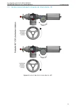
Direction of rotation handwheel for closing the valve, Failsafe direction „CW“ . . . . . . . . . . . . . . 11

7.2.4

Direction of rotation handwheel for closing the valve, Failsafe direction „CCW“. . . . . . . . . . . . . 12

7.2.5

Required torque on the handwheel . . . . . . . . . . . . . . . . . . . . . . . . . . . . . . . . . . . . . . . . . 13

7.3

Mechanical default setting, preparation . . . . . . . . . . . . . . . . . . . . . . . . . . . . . . . . . . . . . . . . . . . 13

7.4

Setting the end positions . . . . . . . . . . . . . . . . . . . . . . . . . . . . . . . . . . . . . . . . . . . . . . . . . . . . 13

7.5

Setting the mechanical end stop . . . . . . . . . . . . . . . . . . . . . . . . . . . . . . . . . . . . . . . . . . . . . . . 13

7.6

Adjusting of Failsafe speed . . . . . . . . . . . . . . . . . . . . . . . . . . . . . . . . . . . . . . . . . . . . . . . . . . . 14

7.6.1

Setting procedure:. . . . . . . . . . . . . . . . . . . . . . . . . . . . . . . . . . . . . . . . . . . . . . . . . . . . 15

7.7

Final work . . . . . . . . . . . . . . . . . . . . . . . . . . . . . . . . . . . . . . . . . . . . . . . . . . . . . . . . . . . . . . 16

8

The control unit . . . . . . . . . . . . . . . . . . . . . . . . . . . . . . . . . . . . . . . . . . . . . . . . . . . . . . . . . . . . . . 16

9

Maintenance . . . . . . . . . . . . . . . . . . . . . . . . . . . . . . . . . . . . . . . . . . . . . . . . . . . . . . . . . . . . . . . . 17

10 Technical data Failsafe brake . . . . . . . . . . . . . . . . . . . . . . . . . . . . . . . . . . . . . . . . . . . . . . . . . . . . . 18

10.0.1 CM03F(S)QT . . . . . . . . . . . . . . . . . . . . . . . . . . . . . . . . . . . . . . . . . . . . . . . . . . . . . . . 18
10.0.2 CM06F(S)QT . . . . . . . . . . . . . . . . . . . . . . . . . . . . . . . . . . . . . . . . . . . . . . . . . . . . . . . 18
10.0.3 CM12F(S)QT . . . . . . . . . . . . . . . . . . . . . . . . . . . . . . . . . . . . . . . . . . . . . . . . . . . . . . . 18

11 Spare parts . . . . . . . . . . . . . . . . . . . . . . . . . . . . . . . . . . . . . . . . . . . . . . . . . . . . . . . . . . . . . . . . . 18

12 Lubricant recommendation / Lubricant requirements . . . . . . . . . . . . . . . . . . . . . . . . . . . . . . . . . . . . 18

12.1

Lubricant points F(S)QT. . . . . . . . . . . . . . . . . . . . . . . . . . . . . . . . . . . . . . . . . . . . . . . . . . . . . 18

12.2

Basic lubricant service interval . . . . . . . . . . . . . . . . . . . . . . . . . . . . . . . . . . . . . . . . . . . . . . . . 19

13 Training. . . . . . . . . . . . . . . . . . . . . . . . . . . . . . . . . . . . . . . . . . . . . . . . . . . . . . . . . . . . . . . . . . . . 19

14 Mode of operation F(S)QT . . . . . . . . . . . . . . . . . . . . . . . . . . . . . . . . . . . . . . . . . . . . . . . . . . . . . . . 20

14.1

CM03 F(S)QT . . . . . . . . . . . . . . . . . . . . . . . . . . . . . . . . . . . . . . . . . . . . . . . . . . . . . . . . . . . 20

14.2

CM06 F(S)QT . . . . . . . . . . . . . . . . . . . . . . . . . . . . . . . . . . . . . . . . . . . . . . . . . . . . . . . . . . . 21

2

Содержание CM03

Страница 1: ...Operating Manual 90 ACTUSAFE CMF S QT OM ENGLISH Failsafe QT 16xx V2 00 2022 03 01 ...

Страница 2: ...sition of the control unit 9 6 3 Electrical connection 9 7 Commissioning 9 7 1 General information 9 7 2 Manual operation 9 7 2 1 Activate manual operation 10 7 2 2 Deactivate manual operation 10 7 2 3 Direction of rotation handwheel for closing the valve Failsafe direction CW 11 7 2 4 Direction of rotation handwheel for closing the valve Failsafe direction CCW 12 7 2 5 Required torque on the hand...

Страница 3: ...ault settings preparation 30 5 4 User Level and Permissions 31 5 5 End limit setting 31 5 5 1 End limit OPEN 31 5 5 2 End limit CLOSE 33 5 6 Final works 34 6 Control Unit 34 6 1 Operating unit 34 6 2 Display elements 35 6 2 1 Graphic display 35 6 2 2 LED Display 35 6 3 Operation 36 6 4 Welcome Menu 36 6 4 1 Operation mode 38 6 4 2 Configuration 38 6 4 3 Configuration example 39 6 4 4 TEACHIN 40 7 ...

Страница 4: ...linear actuators 40 to 60 C 77 15 4 Basic lubricant service interval 77 16 Training 77 17 Original Declaration of Incorporation of Partly Completed Machinery 78 18 Declaration of Conformity 79 19 Declaration of Conformity 80 20 Technical data 81 20 1 Binary outputs 81 20 2 Binary inputs 81 20 3 Analog inputs 83 20 4 Analog output 84 20 5 Auxiliary voltage input and output 84 20 6 Connections 85 20...

Страница 5: ...supervision of an electrician in accordance with electro technical regulations WARNING Working on the opened and energized actuator may only be carried out if it is ensured that there is no risk of explosion for the duration of the work WARNING When working in potentially explosive areas heed European Standards EN 60079 14 In stalling Electrical Systems in Explosion Endangered Areas and EN 60079 1...

Страница 6: ...to operate appropriate fittings when a Failsafe functionality is required Appropriate fittings are all kinds of fittings that require a 90 movement to operate butterfly valves ball valves taps in general etc In the event of a power failure or if the Failsafe function is triggered deliberately the 90 ACTUSAFE actuator shifts the fitting to the Failsafe position using the built in energy storage dev...

Страница 7: ...it components are permanently engaged While moving against the Failsafe direction the electric motor has to move both the fitting and the energy storage device spring for the Failsafe stroke If the supply for the operating current brake is interrupted by a power failure or intentionally to trigger a Failsafe stroke the actuator will no longer be held and the potential energy stored in the spring w...

Страница 8: ...rection of rotation when looking at the fitting shaft see Figure 3 or Failsafe CW clockwise direction of rotation It is even possible to subsequently change the Failsafe direction separate manual available see Figure 4 which requires some assembly work Having this conversion performed at our plant is recommended however Failsafedirection Figure 3 Failsafe direction counter clockwise CCW Failsafedi...

Страница 9: ...oving in Failsafe direction In Failsafe mode the actuator can only move in Failsafe direction When the electrical holding brake is released the actuator moves against the end limit by spring In this case the end limit is generally torque dependent The torque in end position is build up by the residual spring torque Travel depended positioning of the end limit is possible by adjusting the mechanica...

Страница 10: ...ition Make sure the fitting is in the same position as the actuator For a Failsafe open actuator the fitting has to be completely open For a Failsafe close actuator the fitting has to be completely closed In general heed the following instructions Clean the bare parts on the actuator coated with rust protectant Clean the mounting surface for the fitting thoroughly Lightly grease the fitting shaft ...

Страница 11: ...8 29 90 15 71 100 17 45 CM06F S QT100 16 64 90 9 42 100 10 47 CM06F S QT200 16 57 90 31 42 100 34 9 CM06F S QT300 16 62 90 39 27 100 43 63 CM06F S QT500 16 64 90 60 87 100 67 63 CM12F S QT1200 32 125 90 78 54 100 87 27 NOTE When commissioning and each time after dismounting the actuator the electrical end positions have to be reset see operating manual ACTUSMART CM V1 2 section 5 5 page 31 7 2 Man...

Страница 12: ...ator For easier clutch engagement move the hand wheel easily back and forth Through the engagement the actuator is automatically electrically disabled and the display shows manual override 7 2 2 Deactivate manual operation The following steps are done to exit the manual mode and to enable the automatic mode again the actuator must be driven to the Failsafe position by handwheel the coupling rod is...

Страница 13: ... ACTUSAFE CMF S QT OM ENGLISH Failsafe QT 16xx V2 00 2022 03 01 7 Commissioning 7 2 3 Direction of rotation handwheel for closing the valve Failsafe direction CW Figure 6 Roation of direction for Failsafe direction CW 13 ...

Страница 14: ...ating Manual 90 ACTUSAFE CMF S QT OM ENGLISH Failsafe QT 16xx V2 00 2022 03 01 7 2 4 Direction of rotation handwheel for closing the valve Failsafe direction CCW Figure 7 Roation of direction for Failsafe direction CCW 14 ...

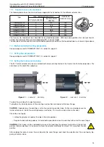
Страница 15: ... 7 5 Setting the mechanical end stop The 90 Failsafe actuator only has one limited mechanical end stop that limits the travel at the Failsafe end position The end stop is at the end of the spring cup Figure 8 1 Locknut 2 End stop Figure 9 1 Locknut 2 End stop To adjust the end stop first undo the locknuts To lengthen the stroke by means of the end stop unscrew the end stop out of the cover flange ...

Страница 16: ...ailsafe speed When delivered the Failsafe speed is set to minimum After mounting the actuator to a valve and after conducting a test run the Failsafe speed can be increased if neces sary CAUTION Valve or piping equipment may be damaged if the actuation speed is too high WARNING All adjustment work may only be performed with the actuator disconnected from the power supply Due to this requirement th...

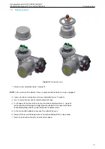
Страница 17: ...ding Figure 11 page 16 3 Insert a 3mm allen key into the radial borehole of flange 4 Turn flange with the help of the allen key in direction according Figure 11 page 16 Half of possible rotating angle will approximately double Failsafe speed of actuator While holding flange with key in desired position retighten screws 5 In the version with handwheel reconnect the cable to the cover 6 Remount the ...

Страница 18: ...ACTUSAFE CMF S QT OM ENGLISH Failsafe QT 16xx V2 00 2022 03 01 Figure 11 Adjusting speed 7 7 Final work See operating manual ACTUSMART CM V1 2 section 5 6 page 34 8 The control unit See operating manual ACTUSMART CM V1 2 section 6 page 34 18 ...

Страница 19: ...tion Lengthening in the running time may also be caused by an increased torque requirement for the fitting after long down times WARNING The actuator has a pre stressed coil spring or disk spring assembly Improper dismounting may lead to both damage to the actuator as well as serious injuries If maintenance work is needed re quiring the actuator to be dismounted contact SCHIEBEL Antriebstechnik Ge...

Страница 20: ...e relubrication intervals in the operating instructions After relubrication has been carried out 2 3 full strokes must be performed If torque switch off occur the grease nipples must be removed and the strokes repeated NOTE Lubricant can leak out of the lubrication points The grease nipples should be reinstalled in case of removal The spindle nut is or should be lubricated during initial assembly ...

Страница 21: ...ou experience any problems during installation or in doing the adjustment work on site please contact SCHIEBEL Vienna either by telephone on 43 1 66 108 or via internet at www schiebel actuators com so as to avoid any possible faulty operation or damage to the actuators Schiebel recommends only using qualified personnel to do the installation work for Schiebel actuators On special request by SCHIE...

Страница 22: ... IEC 60034 2 5 36 RPM 2 5 36 RPM Mmax 300 Nm Mmax 600 Nm Mavg 150 Nm Mavg 300 Nm Life time 1 200 000 starts 1 200 000 starts CONTINIOUS MODULATING operation CM03 F S QT 30 CM06 F S QT 60 S9 1 800 c h according to IEC 60034 S9 1 800 c h according to IEC 60034 2 5 20 RPM 2 5 20 RPM Mmax 300 Nm Mmax 600 Nm Mavg 100 Nm Mavg 200 Nm Life time 1 200 000 starts 1 200 000 starts NOTE Life time is based on ...

Страница 23: ...34 2 5 30 RPM 2 5 30 RPM 2 5 30 RPM 2 5 30 RPM Mmax 1 000 Nm Mmax 2 000 Nm Mmax 3 000 Nm Mmax 5 000 Nm Mavg 500 Nm Mavg 1 000 Nm Mavg 1 500 Nm Mavg 2 500 Nm Life time 1 200 000 starts 500 000 starts 500 000 starts 250 000 starts CONTINIOUS MODULATING operation CM06 F S QT 100 CM06 F S QT 200 CM06 F S QT 300 CM06 F S QT 500 S9 1 800 c h according to IEC 60034 S9 1 800 c h according to IEC 60034 S9 ...

Страница 24: ...s Work on the electrical system or equipment must be carried out only in accordance with electrical regulations by a qualified electrician himself or by specially instructed personnel under the control and supervision of a qualified electrician CAUTION Maintenance instructions must be observed as otherwise the safe operation of the actuator cannot be guaranteed WARNING Failure to follow the warnin...

Страница 25: ...ART CM series carries a serial number The serial number is a 10 digit number that begins with the year and that can be read from the type label see Figure 14 of the actuator the type label is located next to the handwheel see Figure 15 Using this serial number SCHIEBEL can uniquely identify the actuator type size design options technical data and test report Figure 14 Type label 1 Figure 15 1 Type...

Страница 26: ...ot damaged and remain properly fastened Improper assembly may lead to water ingress and to failures of the actuator CAUTION The cover of the control unit the operating unit see Figure 13 page 23 must not be opened NOTE Allow a certain sag in the connector cables before reaching the screwed cable glands so that water can drip off from the connector cables without running to the screwed cable glands...

Страница 27: ... off duty open loop control 25 60 C Modulating duty closed loop control 25 60 C explosion proof version 20 40 C acc EN 60079 0 explosion proof version with extended temperature range 40 60 C CAUTION The maximum operating temperature can also depend on further order specific components Please refer to the technical data sheets to confirm the as delivered product specifications 2 9 Delivery conditio...

Страница 28: ...rage of actuators Store actuators in well ventilated dry premises Protect against floor dampness by storing actuators on wooden grating pallets mesh boxes or shelves Protect the actuators against dust and dirt with plastic foil Actuators must be protected against mechanical damage The storage temperature must be between 20 C and 40 C It is not necessary to open the controller of the actuator for s...

Страница 29: ...connec tion 6 ground connection Installation work of any kind on the actuator may only be performed by qualified personnel 4 1 Mechanical connection see Figure 21 page 27 Check whether the valve flange actuator flange and valve shaft correspond to the shaft connector of the actuator For output type Am threaded bushing with bore check whether the thread of the valve matches the thread of the actuat...

Страница 30: ...tion of the operating unit can be rotated in 90 steps CAUTION During installation the position of the control unit in relation to direct sunlight must be observed It is recommended to protect the unit from direct sunlight roof installation position to avoid possible malfunctions 90 90 180 Figure 22 Disconnect the actuator and control system from the power supply To prevent damage to the electronic...

Страница 31: ...requency is consistent with the connection data see type label Figure 14 page 23 The connection of electrical wiring must follow the circuit diagram This can be found in the appendix of the docu mentation The circuit diagram can be ordered from SCHIEBEL by specifying the serial number NOTE When using options such as a Profibus connection the relevant guidelines must be followed 4 3 1 Power supply ...

Страница 32: ... ensure that the actuator is correctly assembled and electrically connected see section 4 page 27 NOTE Remove silica gel from the connection compartment 5 1 General CAUTION During commissioning and after every disassembly of the actuator the electric end positions see section 5 5 page 31 must be reset 5 2 Manual operation The use of a differential gearbox in the handwheel assembly makes mechanical...

Страница 33: ... level Please refer to section 7 6 for more information about the user levels 5 5 End limit setting A detailed description of the operation of the ACTUSMART CM controller can be found in section 6 3 page 36 NOTE Please make sure that the current user level has the permission to edit the end limits 5 5 1 End limit OPEN Set the selector switch and control switch to the center position Figure 25 1 Se...

Страница 34: ...avel dependent switch off occurs in the end position CAUTION Please note that during motor operation only torque monitoring remains active as travel adjust ment will happen subsequently Therefore please check beforehand whether the maximum torque has been already parameterised Absolute and relative values on the display will change continuously along with position changes Figure 33 Figure 34 Manua...

Страница 35: ...e position Thus the line TEACHIN disappears Figure 36 Figure 37 In order to confirm the end position save slightly flip up the selector switch towards and let it snap back to its neutral position Figure 38 Figure 39 Figure 40 This changes the bottom line of the display for SAVE to EDIT and the end position is stored Figure 41 Figure 42 5 5 2 End limit CLOSE Use menu item P 1 2 End limit End limit ...

Страница 36: ...the actuator 6 1 Operating unit Operation relies on two switches the control switch and a padlock protected selector switch Information visualization is provided by 4 integrated indicator lights as well as the graphic display For better visibility switch symbols are on the cover Figure 43 1 Selector switch 2 Control switch 3 Graphic display 4 LED display The controller switches serve on the one ha...

Страница 37: ...tus When using the option identification a customer specific label is shown at the bottom of the display e g PPS Number 1 2 3 Figure 45 1 Status 2 Operation mode 3 Position CAUTION The display should not be exposed to direct sunlight over a long peroid risk of a defect in combi nation with very high temperatures 6 2 2 LED Display To provide users with better status information basic status data is...

Страница 38: ... OFF Red Infrared connected Infrared data transmission Infrared ON not connected 6 3 Operation The actuator is operated via the switches located on the controller selection and control switch All actuator settings can be entered with these switches Furthermore configuration is also possible via the IR interface or the Bluetooth Interface see section 9 page 72 Flip the switch up or down to regulate...

Страница 39: ...Operating Manual 90 ACTUSAFE CMF S QT OM ENGLISH Failsafe QT 16xx V2 00 2022 03 01 6 Control Unit Figure 51 Welcome menu 1 2 Figure 52 Welcome menu 2 2 39 ...

Страница 40: ...itch is used to scroll up or down the menu according to internal symbolism From the neutral position towards you reach the status and history data areas Towards the symbols you reach the parameter menu Here the selection switch either confirms or rejects the current input according to associated symbolism Selector switch in the REMOTE position The control switch gives you access to status history ...

Страница 41: ...4 3 Configuration example By way of example we will change parameter P20 6 wireless from 0 wireless off to 2 Bluetooth communication on Thus the Bluetooth connection is activated for a short time and then deactivated again automatically The operating and control switch must be in the neutral position Figure 55 1 Selector switch red 2 Control switch black Now move the control switch down towards un...

Страница 42: ... off to 2 Bluetooth Figure 63 Figure 64 If the value changes to 1 confirm the selection by flipping halfway up the selector switch towards and letting it snap back to its neutral position see Figure 58 til Figure 60 Figure 65 Figure 66 This changes the bottom line of the display from SAVE to EDIT and the parameter is stored 6 4 4 TEACHIN Furthermore certain parameters end positions intermediate po...

Страница 43: ...ual operation by hand wheel the actuator can be motor driven with the control switch to the desired position see section 34 Figure 34 page 32 Figure 67 CAUTION Please note that during motor operation only torque monitoring remains active as travel adjust ment will happen subsequently Therefore please check beforehand whether the maximum torque has been already set After reaching the desired to be ...

Страница 44: ...position P1 3 End limit Switch off Open 0 By travel The actuator uses end position signals to switch off and report the end position Attention For failsafe actuators in failsafe direction not applicable End limit by travel in failsafe position only possible by changing the mechanical connection to the valve 1 By torque The actuator signals the end position or stops the motor only after reaching th...

Страница 45: ... OFF is reached when closing 0 and will be left when opening only at 1 i e a re closing can only take place after leaving this hysteresis P1 9 End limit Ramp 0 1 100 When approaching the end position the speed is reduced P1 10 End limit Range 0 100 End position range for torque P1 3 P1 4 Permissible range in which the torque is to be achieved If the actuator comes to the end of the end position ra...

Страница 46: ...Ramp optional The start ramp can be set separately for each operation mode Thus a 100 start ramp means that the motor attains its maximum speed in about a second Higher speeds see section 7 3 lead to shorter runtimes If the ramp is set below 100 the starting time increases in an inversely proportional fashion Menu item Sub menu item poss setting Notes comments P5 1 Ramp Local 1 100 Start ramp for ...

Страница 47: ...ead write setting per pa rameter the menu items can only be seen or edited if the current user level is equal or higher than the required user level Parameters are assigned default user levels These may be changed with the SmartTool2 if the set user level in the SmartTool2 is equal or higher than the current user level setting of the parameter group Figure 68 Actuator parameters on the SmartTool2 ...

Страница 48: ...enu item U User level after 3 minutes of inactivity or upon restarting the actuator Password will be prompted if the set user level is higher than the currently active user level P7 2 User Level Bus 0 6 Sets the user level on access via Bus P7 3 User Level Remote Display 0 6 Sets the user level on the remote display P7 4 User Level Change Password 6 digit Changes the password of the current active...

Страница 49: ...r position intermediate position are active within this range see P10 1 P8 7 Position Intermed pos 5 TEACHIN 0 100 see above P8 8 Position Intermed pos 6 TEACHIN 0 100 see above P8 9 Position Intermed pos 7 TEACHIN 0 100 see above P8 10 Position Intermed pos 8 TEACHIN 0 100 see above P8 11 Position Dead Band 0 10 Tolerance range for the position deviation intermediate position actual position wher...

Страница 50: ...ween 49 5 and the outer hysteresis mirrored on the ordinate which is 51 5 in this case NOTE Please be aware that a 100 setting for hysteresis will cause oscillation due to overlapping thresholds 7 8 Parameter group Binary inputs The controller is equipped with 5 freely configurable binary inputs Please find further information on technical data of the binary inputs in section 20 2 page 81 Binary i...

Страница 51: ...ration also in local mode 20 Positioner off Positioner lock 21 Deblock Local The actuator may be operated only with a switched signal 22 Block Local as Release Local but active low 23 Emerg Open Lock Trigger lock OPEN in LOCAL and REMOTE mode Actuator moves with the highest priority to OPEN command continues internally active after reaching the end position OPEN Dropping only with LOCK OFF Supply ...

Страница 52: ...avel Close inv reserved for future use 45 Failsafe lock reserved for future use only for Failsafe actuators 46 Failsafe lock inv reserved for future use only for Failsafe actuators 47 Intermed pos Bit0 Intermed pos Bit0 to Intermed pos Bit3 allow to signal intermediate positions 1 to 16 through a bit pattern binary to decimal decimal value 1 corresponds to the Int pos Bit3 is the MSB E g to move t...

Страница 53: ...s been switched off 10 Torque Switch off torque was reached in either Closed or Open direction 11 Travel Open The Open end position has been reached 12 Travel Closed The Closed end position has been reached 13 Pos Int 1 Position Intermediate position 1 14 Pos Int 1 Position Intermediate position 1 15 Pos Int 2 Position Intermediate position 2 16 Pos Int 2 Position Intermediate position 2 17 Pos In...

Страница 54: ...on 1 The width of the interval is set with the parameter P8 6 47 Pos Int2 Position Intermediate position 2 The width of the interval is set in parameter P8 6 48 Pos Int3 Position Intermediate position 3 The width of the interval is set in parameter P8 6 49 Pos Int4 Position Intermediate position 4 The width of the interval is set in parameter P8 6 50 Pos EmergPos Position emergency position The wi...

Страница 55: ... empty loss of time date or counter values possible 83 Undervoltage Fault The input voltage is too low The motor is switched off until the input voltage is in the regular voltage range 84 Undervoltage Switchoff The input voltage dropped below the lower threshold multiple times The motor is turned off for 5 minutes This error can be acknowledged by switching the selector switch to OFF or by turning...

Страница 56: ...f P10 15 Bin Output Output 8 see Output 1 P10 16 Bin Output Output 8 Konf see Output 1 conf CAUTION When using the parameters torque dependent OPEN or torque dependent CLOSED see section 7 1 page 42 items P1 3 and P1 4 the actuator will only be open or closed when the set torque and the asso ciated end position is reached If the end position is not reached a torque error is reported see section 6 ...

Страница 57: ... end torque 0 mA output start torque 100 Open mA output end 5 Torque 3 mA output corresponds to the actual torque value torque 150 Close mA output start torque 0 mA output center torque 150 Open mA output end 6 Torque 4 mA output corresponds to the actual torque value torque 150 Close mA output end torque 0 mA output start torque 150 Open mA output end 7 Ext Setpoint 1 Passes on the mA input signa...

Страница 58: ... In CLOSED direction position in from which the step mode operation should start P12 7 Step mode function End Close 0 100 In CLOSED direction position in of which the step mode operation should end P12 8 Step mode function ON Time Close 0 1 60 Runtime in Closed direction P12 9 Step mode function OFF Time Close 0 2 60 Pause time in Closed direction P12 10 Step mode function Timebase 0 Seconds Time ...

Страница 59: ...ing smaller reachable deadband A 100 setting disables this gradient P13 6 Positioner Live zero detect 0 Ignore The setpoint monitoring monitoring the setpoint to below approximately 2 mA loss of signal is disabled 1 Stop Actuator stops on signal failure 2 Open On signal failure actuator moves the OPEN position 3 Close Actuator moves on signal failure to the CLOSED position 4 Emerg pos On signal fa...

Страница 60: ...ther than the end position OPEN The area e0 100 is just passed through Use the parameter e0 to define the end of the allowable control range of the valve P13 13 Positioner Begin setp a1 0 0 25 0 2 0 Below this value the end position CLOSED is controlled In the range 0 a1 cannot be controlled end position tolerance The initial setpoint a1 is associated with a small hysteresis 1 4 of the deadband P1...

Страница 61: ... controller corresponds to the position setpoint of the actuator The positioning tracking of the actual position to the setpoint is done by the positioner see 7 12 2 Speed The output of the PID controller corresponds to the change of the position setpoint speed of the actuator The positioning tracking of the actual position to the setpoint is done by the positioner see 7 12 2 Position Change The o...

Страница 62: ... position Actuator moves on signal failure of external actual values to the EMERGENCY position see param P13 7 P14 13 PID controller Calibration of ext actual value 10 0 10 0 Calibration process By applying 20 mA to the external actual value input this parameter is corrected until the readout matches to 20 mA P14 14 PID controller Process begin 32768 32767 Mantissa of the real process variable beg...

Страница 63: ...aracteristic Menu item Sub menu item poss setting Notes comments P17 1 Characteristic Torque Open 0 Off The torque characteristic curve is disabled for the OPEN direction 1 On The torque characteristic curve is enabled for the OPEN direction 2 Local Remote only The torque characteristic curve is enabled for the OPEN direction only in LOCAL and REMOTE mode while disabled in the EMERGENCY mode P17 2...

Страница 64: ...eed Open 0 Off The speed characteristic curve is disabled for the OPEN direction 1 On The speed characteristic curve is enabled for the OPEN direction P17 4 Characteristic Speed Closed 0 Off The speed characteristic curve is disabled for the CLOSED direction 1 On The speed characteristic curve is enabled for the CLOSED direction 7 15 3 Valve characteristic With this characteristic curve the mappin...

Страница 65: ...em poss setting Notes comments P18 1 Identification PPS number 15 digits Used to enter a PPS number This is displayed in the bottom line CAUTION Param P20 5 must be set to 0 7 17 Parameter group System parameters Used for actuator configuration Most of these parameters are used to display crucial information about the actuator configuration for servicing thus only visible for user level service or...

Страница 66: ...tion in section 7 1 on page 42 P19 56 System Parameters LCD Inverse 0 1 Inverts the display pixels 7 18 Parameter group Miscellaneous Menu item Sub menu item poss setting Notes comment P20 1 Miscellaneous Language 0 German Defines the menu language 1 English 2 Russian 3 Czech 4 Spanish 5 French 6 Italian 7 Danish 8 Hungarian 9 Turkish 10 Greek 11 Polish 12 Serbian 13 Croatian 14 Bulgarian 15 Dutch...

Страница 67: ...meters are adopted as workshop parameters P20 5 Miscellaneous Info line 0 15 The bottom line of the display shows various diagnostic values P20 6 Miscellaneous Wireless 0 Off The infrared and bluetooth connection is disabled 1 Infrared The infrared connection is active for about 3 minutes unless communication is detected 2 Bluetooth The Bluetooth connection is active for about 3 minutes unless com...

Страница 68: ...ed Remote Close 2 4 P4 5 Speed Emerg Open 2 4 P4 6 Speed Emerg Close 2 4 P4 7 Speed Torquedep oper 2 4 P4 8 Speed Minimal 2 4 P5 1 Ramp Local 2 4 P5 2 Ramp Remote 2 4 P5 3 Ramp Emergency 2 4 P6 2 Control Ready delay 2 4 P6 5 Control 24V Output 2 4 P6 6 Control Min Impuls 2 4 P6 17 Control Remote Display 2 4 P7 1 User Level Local 2 4 P7 2 User Level Bus 2 4 P7 3 User Level Remote Display 2 4 P7 4 U...

Страница 69: ... 2 4 P10 11 Bin Output Output 6 2 4 P10 12 Bin Output Output conf 6 2 4 P10 13 Bin Output Output 7 2 4 P10 14 Bin Output Output conf 7 2 4 P10 15 Bin Output Output 8 2 4 P10 16 Bin Output Output conf 8 2 4 P11 1 Analog Signal Function 1 2 4 P11 2 Analog Signal Begin 1 at 0 2 4 P11 3 Analog Signal End 1 at 100 2 4 P11 4 Analog Signal Calib 20mA 1 2 4 P11 5 Analog Signal Function 2 2 4 P11 6 Analog ...

Страница 70: ...ial 2 4 P14 9 PID controller Offset 2 4 P14 12 PID controller Live zero detect 2 4 P14 13 PID controller Cal ext act val 2 4 P14 14 PID controller Process begin 2 4 P14 15 PID controller Process end 2 4 P14 16 PID controller Process comma shift 2 4 P14 17 PID controller Process unit 2 4 P14 18 PID controller Dead band 2 4 P16 1 Stroketest Stroketest 2 4 P16 2 Stroketest Start position 2 4 P16 3 St...

Страница 71: ...1 3 P20 11 Miscellaneous Daylight saving time 1 3 8 Status area The status area presents current process and diagnostic data In this area data is read only To access the status area move the control switch in the direction where the selector switch should be in the neutral position or in the remote position The status area is divided into 2 sub areas Status History 8 1 Status 8 1 1 Status binary o...

Страница 72: ...optional PID controler In the analogue output out only the control signal is shown regardless of whether the output current actually flows or not interruption of the current loop 1 2 3 4 Figure 79 1 Input 1 2 Input 2 3 Output 4 All values in mA 8 1 4 Status absolute values This status displays the absolut position of the actuator 1 2 3 4 Figure 80 1 Absolute value of the position unit 2 Relative v...

Страница 73: ...l number of the control unit 8 1 7 Status meter readings Figure 83 1 Counters for power on cycles power on time and motor run time 2 Actual date and time 8 2 History History shows the last 20 history entries In addition to the plain text entry the time since the last history entry and in case of an error the error value is also provided Please note that the actuator can only calculate time if ener...

Страница 74: ...ace is protected from strong disturbances which may other wise compromise the communication Before mounting the infrared adapter clean the surface of the infrared interface with a damp cloth When the infrared interface is enabled it is indicated by LED L5 see section 6 2 2 Figure 85 page 35 The infrared interface can be enabled in the menu item P20 6 Figure 85 1 Infrared connection 10 Bluetooth co...

Страница 75: ... downtime periods operate the actuator at least every 3 months For actuators with output types A B and C according to DIN 3210 A B1 B2 and C according to DIN ISO 5210 re lubricate at least every 6 months on existing grease fittings see section 15 3 page 77 Actuators are designed for installation in any position see section 2 5 page 24 Therefore the main body is not equipped with a level indication...

Страница 76: ...al 24 VDC auxiliary voltage or loss of phase L2 7 Ready Information Written to the history after all errors are gone 8 Power On Information Is written to the history after power on the actuator even if there are some errors 9 Power supply Fault 21 Power supply OK Alarm No power supply to the power electronics when the controller is powered from the auxiliary power input Defect of power electronics...

Страница 77: ...SmartTool2 54 PVST Error 55 PVST OK Information The last PVST was not successful 56 Internal Comm Fault E Error 57 Internal Comm Fault E OK Warning Communication error between remote display and main display Cable to from remote display to EB2_2 EB2_2 to EB2_1 or EB2_1 to main display broken Also one of the boards may be faulty 58 Undervoltage Error Alarm The input voltage is below the minimum thr...

Страница 78: ...e provide us with the serial number of the actuator see section 2 2 page 23 Check the separate break down image and separate list of spare parts 15 Lubricant recommendation lubricant requirements CAUTION Please note that safety precautions such as the use of personal protective equipment PPA may have to be followed Please consult the safety datasheet in section 8 of the product in question 15 1 Ma...

Страница 79: ...ely high above 50 C 0 7 Extremely low below 25 C 0 9 Output speed on actuator main shaft High speed over 80 rpm 0 8 Utilisation relative to rated power Very high over 90 0 8 High between 80 and 90 0 9 Application example Extremely low DT extremely low ambient temperature high speed 87 utilization 0 8 0 9 0 8 0 9 0 51 reduction factor Lubrication maintenance interval 10 years 0 51 5 1 years 62 mont...

Страница 80: ...rtly completed machinery referred to in Annex VII Part B has been prepared The manufactor commits to electronically submitting the documents for the incomplete machine to the competent national authority upon request For the preparation of the technical documents is authorized Head of mechanical Engineering Schiebel Antriebstechnik Gesellschaft m b H Josef Benc Gasse 4 A 1230 Vienna This partly co...

Страница 81: ... Actusmart and following types r CM03 r CM03 FS r CM06 r CM06 FS meets the requirement of the EC directive 2014 30 EU EMV directive and complies with the following harmonised standards in the version valid at sigature date EN 61000 6 2 2005 EN 61000 6 4 2014 and are also consistent with the EC directive 2014 35 EU Low voltage directive in consideration of the respective operating instructions and ...

Страница 82: ...lies with the following harmonised standards in the version valid at sigature date EN 60079 0 2012 EN 60079 1 2014 EN 60079 7 2015 EN ISO 80079 36 2016 EN ISO 80079 37 2016 For the above listed actuators a type examination certificate TUV A13ATEX0006X issued by TÜV Austria Services GMBH is available TÜV Austria Services GmbH A 1230 Wien NB 0408 Type examination certification FTZU CZ 716 07 Ostrava...

Страница 83: ... 4 A Fuse Fuse FL2 see Figure 89 page 81 4 A slow Littelfuse 454 NANO2 Slo Blo Binary outputs with external supply are separated from other controllers via optocouplers It is allowed to connect binary outputs in parallel If the outputs have the same setting see chapter 7 9 the current of each output may be added together If the settings of the outputs are different a hardwired logical OR is realiz...

Страница 84: ... Input current Jumpers JP1 JP3 can be used to interconnect the binary inputs to groups with separate earths Figure 91 5 inputs with same common Figure 92 2 separated groups of 2 inputs with same ground Input IN3 is disabled Figure 93 3 separated inputs Inputs IN2 and IN4 are disabled Figure 94 3 inputs with same common and 1 separated input Input IN4 is disabled 84 ...

Страница 85: ...V e g for dry contacts 3 2 1 JP3 3 2 1 JP2 3 2 1 JP1 3 2 1 JP3 3 2 1 JP2 3 2 1 JP1 Com1 IN1 4 3 Com5 Com3 IN3 IN5 7 5 6 8 Com IN1 4 3 IN4 IN2 IN3 IN5 7 5 6 8 3 2 1 JP3 3 2 1 JP2 3 2 1 JP1 Com IN1 4 3 IN4 IN2 IN3 IN5 7 5 6 8 1 2 INT INT 3 2 1 JP3 3 2 1 JP2 3 2 1 JP1 Com1 IN1 4 3 Com5 Com3 IN3 IN5 7 5 6 8 24V 24V 24V 24V 24V Ext 24V Common Interne 24V Ext Ext Common Bild speichern Markierungsrahmen ...

Страница 86: ...4 20 mA two wire transmitter Figure 102 Current source Figure 103 Current sink Ground potential is the potential of the control unit and the auxiliary supply see chapter 20 5 20 5 Auxiliary voltage input and output Input voltage range auxiliary voltage input 20 30 VDC Maximum current consumption auxiliary voltage input 500 mA Maximum current consumption in power save mode 120 mA auxiliary voltage ...

Страница 87: ... the mA output are not enabled when activating the respective currents must be added to the total current consumption 20 6 Connections 20 6 1 Connections for non explosion proof version Power motor Industrial plug with 6 pins Screw connection 16 A max 2 5 mm2 AWG14 Control signals Industrial plug with 24 pins Screw connection 16 A max 2 5 mm2 AWG14 Optionally contacts are available in crimp or cag...

Страница 88: ...M 2 5 30 RPM Mmax 32 Nm Mmax 64 Nm Mavg 16 Nm Mavg 32 Nm Life time 1 800 000 starts 1 800 000 starts CONTINUOUS MODULATING operation CM03 CM06 S9 1 800 c h according to IEC 60034 S9 1 800 c h according to IEC 60034 2 5 20 RPM 2 5 20 RPM Mmax 32 Nm Mmax 64 Nm Mavg 10 Nm Mavg 20 Nm Life time 1 800 000 starts 1 800 000 starts NOTE life time is based on proper operation and maintenance according to SC...

Страница 89: ... 2 5 20 RPM 2 5 20 RPM Mmax 120 Nm Mmax 250 Nm Mmax 500 Nm Mavg 60 Nm Mavg 125 Nm Mavg 250 Nm Life time 1 800 000 starts 1 200 000 starts 1 200 000 starts CONTINUOUS MODULATING operation CM03 FS 30 5 CM03 FS 50 8 CM03 FS 100 12 S9 1 800 c h according to IEC 60034 S9 1 800 c h according to IEC 60034 S9 1 800 c h according to IEC 60034 2 5 10 RPM 2 5 20 RPM 2 5 20 RPM Mmax 120 Nm Mmax 250 Nm Mmax 50...

Страница 90: ...ng to IEC 60034 S4 1 200 c h max 50 DC according to IEC 60034 S4 1 200 c h max 50 DC according to IEC 60034 2 5 36 RPM 2 5 30 RPM 2 5 30 RPM Fmax 15 kN Fmax 25 kN Fmax 26 kN Favg 7 5 kN Favg 12 5 kN Favg 13 kN Life time 1 800 000 starts 1 200 000 starts 1 200 000 starts CONTINUOUS MODULATING operation CM03 L50 CM03 L100 CM03 L350 NOT AVAILABLE NOT AVAILABLE NOT AVAILABLE NOTE life time is based on...

Страница 91: ...ODULATING operation CM03 LK50 CM03 LK100 CM03 LK120 S9 1 800 c h according to IEC 60034 S9 1 800 c h according to IEC 60034 S9 1 800 c h according to IEC 60034 2 5 20 RPM 2 5 20 RPM 2 5 20 RPM Fmax 15 kN Fmax 30 kN Fmax 60 kN Favg 10 kN Favg 10 kN Favg 20 kN Life time 1 800 000 starts 1 200 000 starts 1 200 000 starts NOTE life time is based on proper operation and maintenance according to SCHIEBE...

Страница 92: ...rent 10Nm 20U min 4 6 A Idle power consumption 6 W typ 18 W max all other dates see output data standard version 21 3 400 V version CM03 Output torque max 32 Nm Average permissible output torque max 16 Nm Setting range of tripping torque 8 32 Nm Setting range of output speed 2 5 72 2 min 1 Travel range max 100 revs Output resolution about 0 25 Supply voltage range AC 3 x 380 480 VAC 10 50 60 Hz No...

Страница 93: ...pendent on the existing hardware options 23 Technical data CM12 The motor brushless DC motor is controlled via integrated power electronics which also provide the supply voltage for the controller 23 1 Standard version CM12 Output torque max 125 Nm Average permissible output torque max 40 Nm Setting range of tripping torque 32 125 Nm Setting range of output speed 2 5 70 min 1 Travel range max 100 ...

Страница 94: ...CMF S QT OM ENGLISH Failsafe QT 16xx V2 00 2022 03 01 24 Characteristic curves 24 1 Characteristic curves CM03 Figure 104 Current draw of the standard version Figure 105 Current draw of the 24 VDC version Figure 106 Current draw of the standard version 94 ...

Страница 95: ...0 ACTUSAFE CMF S QT OM ENGLISH Failsafe QT 16xx V2 00 2022 03 01 24 Characteristic curves 24 2 Characteristic curves CM06 Figure 107 Current draw of the standard version Figure 108 Current draw of the standard version 95 ...

Страница 96: ...24 Characteristic curves Operating Manual 90 ACTUSAFE CMF S QT OM ENGLISH Failsafe QT 16xx V2 00 2022 03 01 24 3 Characteristic curves CM12 Figure 109 Current draw of the standard version 96 ...

Страница 97: ...CM03 FSQT ...

Страница 98: ...CM06 FSQT ...

Страница 99: ...EBEL Antriebstechnik Gesellschaft m b H Josef Benc Gasse 4 A 1230 Wien Tel 43 1 66 108 0 Fax 43 1 66 108 4 info schiebel actuators com www schiebel actuators com OM ENGLISH Failsafe QT 16xx V2 00 2022 03 01 ...

Отзывы: