INSTALLING THE AT10.1
14
1.8. MAKING THE DC OUTPUT CONNECTIONS
It is the responsibility of the
installer
of the AT10.1 to provide suitable dc
output, battery, and dc load wiring. Follow these steps to connect the
battery to the AT10.1:
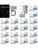
1. Size the dc wiring to minimize voltage drop. The acceptable wire size
depends on your installation. As a guideline, the voltage drop should not
exceed 1% of nominal output voltage at full current. Refer to the table below
to determine the voltage drops for various wire sizes, currents and distances.
WIRE SIZING CHART
VOLTAGE DROP PER 100ft / 30.5m OF WIRE
(for copper at 68 °F / 20 °C)
DC CURRENT
(Amperes)
WIRE SIZE
(AWG)
30 40 50 75 100
#10
3.0V 4.0V 5.0V
not recommended
not recommended
#8
1.9V 2.5V 3.1V
not recommended
not recommended
#6
1.2V 1.6V 2.0V 3.0V
not recommended
#4
0.7V 1.0V 1.2V 1.9V 2.5V
#2
0.5V 0.5V 0.8V 1.2V 1.6V
#0
0.3V 0.4V 0.5V 0.7V 1.0V
EXAMPLE: 100ft / 30.5m of #8 AWG wire at 50A has a 3.1 Volt drop.
2. The AT10.1 is factory wired to regulate the output voltage at the output
terminals. If the total voltage drop is greater than 1% (e.g., 1.3V for a 130
Vdc system), remote sense wiring is recommended, see Section 1.9.
3. Do not run external ac and dc power wiring, feeding the AT10.1, through the
same conduit.
4. All specific requirements of your facility take precedence over these
instructions.
PROCEDURE
1. Use a dc disconnect switch or circuit breaker between the AT10.1 and dc
bus. This device should have lockout capability to allow the AT10.1 to be
disconnected from the dc bus for maintenance.
2. Remove the Plexiglas safety shield.
3. Run the dc wiring to terminals TB1(+) and TB1(-) on the I/O panel board in
the enclosure. Compression lugs, accepting wire sizes #14-1/0 AWG, are
supplied for your convenience.
4. Strip the insulation 0.5in / 12.7mm on the incoming wires. Connect the
wires to the appropriate dc lugs as shown on the next page.
5. Using a flat-head screwdriver, securely tighten the compression screws on
the lugs to 35-50 in-lb / 4.0-5.7 Nm.
6. Reinstall the safety cover after you have made and checked all connections.
Содержание AT10.1 SERIES
Страница 78: ...APPENDIX C 72 Outline AT10 1 Group II Battery Charger NEMA 1 Style 5017 Enclosure JE5025 00...
Страница 79: ...APPENDIX C 73 http www ATSeries net PDFs JE5025 00 pdf...
Страница 80: ...APPENDIX C 74 Outline AT10 1 Group II Battery Charger NEMA 1 Style 5018 Enclosure JE5026 00...
Страница 81: ...APPENDIX C 75 http www ATSeries net PDFs JE5026 00 pdf...
Страница 83: ...APPENDIX C 77 http www ATSeries net PDFs JE5028 99 pdf...
Страница 85: ...APPENDIX C 79 http www ATSeries net PDFs JE5029 99 pdf...
Страница 87: ...APPENDIX C 81 http www ATSeries net PDFs JE5030 29 pdf...
Страница 88: ...APPENDIX C 82 Schematic AT10 1 Group II Battery Charger Standard w o Options JE5032 00...
Страница 89: ...APPENDIX C 83 http www ATSeries net PDFs JE5032 00 pdf...
Страница 90: ...APPENDIX C 84 Schematic AT10 1 Group II Battery Charger w Common Options JE5032 99...
Страница 91: ...APPENDIX C 85 http www ATSeries net PDFs JE5032 99 pdf...
Страница 92: ...APPENDIX C 86 Connection Diagram AT10 1 Group II Battery Charger Standard w o Options JE5034 00...
Страница 93: ...APPENDIX C 87 http www ATSeries net PDFs JE5034 00 pdf...
Страница 94: ...APPENDIX C 88 Connection Diagram AT10 1 Group II Battery Charger w Common Options JE5034 99...
Страница 95: ...APPENDIX C 89 http www ATSeries net PDFs JE5034 99 pdf...
Страница 101: ...USER NOTES 95...