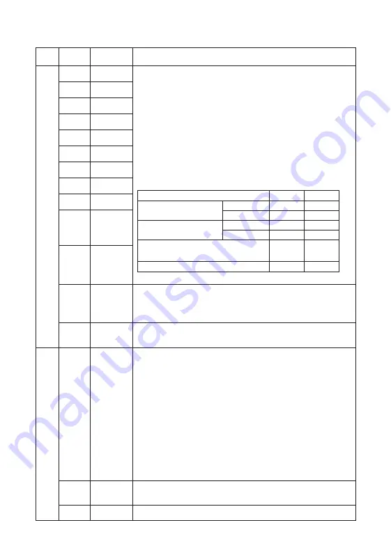
Table 2.8 Function of Control Terminals
(
continued
)
(1) Set various signals towards function parameters 01
.
01~01
.
09
、
01
.
98
、
01
.
99.
(2) Apply SW1 input modes: drain / source switching.
(3) Switch from [short circuit ON] to [short-circuit OFF] of the operation
mode between each digital input terminals and terminals DCM.
(4) Digital input terminals MI7 is set to be pulse input terminal by modify-
ing the function parameter.
Maximum wiring length is 20m
Maximum input pulse is 30kHz: pull the resistor up and down when
connecting to a pulse generator of open collector output.
Refer to the digital input precautions.
100kHz: when connecting to a pulse generator of complementary
outputs.
< Digital input circuit specifications >
(1) Connect output signal power of programmable controller.
(Rated voltage DC +24 V (supply voltage range: DC +22 ~ +27 V) Maxi-
mum 100mA)
(2) Use as load power for transistor output.
Common terminals for digital input signal are absolutely insulated for
ACM. MCM terminals.
MI1
MI2
MI3
MI4
MI5
MI6
MI7
MI8
MI9
Digital input 1
Digital input 2
Digital input 3
Digital input 4
Digital input 5
Digital input 6
Digital input 7
Digital input 8
Digital input 9
FWD
REV
24V
DCM
Forward run-
ning • Stop
command
input
Reverse
running •
Stop
command
input
Auxiliary
control
power
Digital
common
terminal
0V
22V
22V
0V
2V
27V
27V
2V
2.5mA
(4.8mA)
5mA
(8mA)
0.5mA
-
Output the monitor signal of current voltage DC0 ~ 10V or current
voltage DC4 ~ 20mA. Output specification (VO / IO) switches through
SW4 and functional parameters 00.29 on circuit board.
Content of the signal can be chosen from the following through the
setting of function parameter 00.31.
• Output frequency • Output current • Output Voltage
• Output torque •Load factor • Consumption power
• PID feedback value • speed (PG feedback value) • DC bus voltage
• Universal AO • Motor output • Analog output test
• PID command value • PID output value
* Impedance can be connected: Minimum 5kΩ (DC0 ~ 10V output)
(Up to two analog voltmeter can be connected (DC0 ~ 10V, the input
impedance is 10kΩ).)
* Impedance can be connected: Maximum 500Ω (DC4 ~ 20mA output)
* Gain adjustment range: 0 to 300%
Common terminals of analog input and output signals are insulated for
DCM, MCM terminals.
Analog
monitor
Analog
common
terminals
AFM
ACM
DCM
Functions
Categ-
ory
Terminal
symbol
Terminal
name
Item
Operating voltage
(
SINK
)
Operating voltage
(
SOURCE
)
ON Value
OFF Value
ON Value
OFF Value
Maximum
Minimum
Operating current when ON
(Input voltage OV)(Input terminal MI7)
Allowable leakage current when OFF
D
ig
ita
l i
np
ut
An
al
og
o
ut
pu
t
Digital common
terminals
Common terminals for analog input signals and terminal DFM output are
insulated for ACM, MCM terminals.
24
Содержание S3800C Series
Страница 17: ...S3800C S3800C S3800C S3800C S3800C S3800C 14 ...
Страница 18: ...FALSE frequency carrier carrier frequency 00 26 15 ...


