51
Chapter 4 VRM AND EBL FUNCTION
4.3 EXAMPLE OF EBL FUNCTION
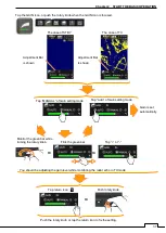
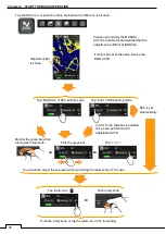
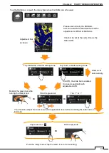
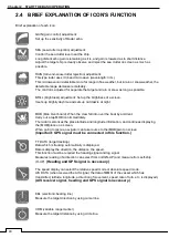
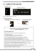
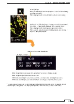
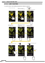
Example: EBL function.
Menu bar disappears after about 10 seconds.
How to change the EBL
Target bearing is displayed.
Flick on the screen, then the EBL line will move along
with the fingertip.
Turn the rotary knob to control the
movement of the EBL line.
Or
****
FOR REFERENCE
****
ABOUT EBL/VRM FUNCTION
The target position and range information can be measured by EBL and VRM function.
Bearing measurement method:
(1) The RELATIVE BEARING which is measured from own ship heading line.
(2) The ABSOLUTE BEARING which is measured from the north line.
Certainly, ABSOLUTE BEARING is calculated by RELATIVE BEARING and GYRO BEARING.
So, to calculate the ABSOLUTE BEARING is necessary a signal from GYRO or GPS compasses.
In case of no external bearing signal, display only RELATIVE BEARING mode.
Target tracking function (TT) and display AIS symbol is necessary the GYRO or GPS compass signal.
When GYRO or GPS compass signal is received, normally azimuth is measured from the north (ABSOLUTE AZIMUTH).
This radar scanner has a microwave BEAM WIDTH is about 5.2 degrees (NKE-1066) or 4 degrees (NKE2044).
So every target echo has more than 5.2 degrees or 4 degrees width for bearing direction.
For above reason, in case of read out the target azimuth, you need set EBL line to the center of the target echo.
RANGE of target echo in any azimuth can be measured by the VRM function from own ship.
Target echo size is proportion to pulse length which transmitted from own ship.
In case of MEASURE SHORT RANGE ECHO using VRM, you need set r
ing to the echo’s nearest point from own ship.
At that point, you can get the correct RANGE for any pulse length.
Содержание SMR-715 series
Страница 1: ...MARINE RADAR EQUIPMENT INSTRUCTION MANUAL...
Страница 2: ......
Страница 15: ...xiii EQUIPMENT APPEARANCE NKE 1066 SCANNER UNIT NKE 2044 SCANNER UNIT...
Страница 29: ...Chapter 1 INSTALLATION 3 1 2 3 DIMENSIONAL DRAWING OF DISPLAY MOUNTING...
Страница 30: ...Chapter 1 INSTALLATION 4...
Страница 31: ...Chapter 1 INSTALLATION 5 1 2 4 EXAMPLES OF DISPLAY MOUNTING DESK TOP INSTALLATION Mounting bracket...
Страница 32: ...Chapter 1 INSTALLATION 6 DESKTOP MOUNTING TEMPLATE Note Please note the paper size 182 257...
Страница 34: ...Chapter 1 INSTALLATION 8 FLUSH MOUNTING TEMPLATE Note Please note the paper size 182 257...
Страница 43: ...Chapter 1 INSTALLATION 17 NKE 2044 2FT SCANNER Fig 1 3 6 3 Fig 1 3 6 4...
Страница 47: ...Chapter 1 INSTALLATION 21 Fig 1 4 1 3...
Страница 51: ...Chapter 1 INSTALLATION 25 Fig 1 4 2 3...
Страница 157: ...131 Chapter 10 AFTER SALE SERVICE 10 4 RADAR FAILURE CHECK LIST SMR...
Страница 159: ...133 Chapter 12 SPECIFICATIONS Chapter 12 SPECIFICATIONS...
Страница 160: ...134 Chapter 12 SPECIFICATIONS 12 1 SCANNER DIMENSION 12 1 1 NKE 1066 4 40 RUBBER PLATE...
Страница 161: ...135 Chapter 12 SPECIFICATIONS 12 1 2 NKE 2044...
Страница 162: ...136 Chapter 12 SPECIFICATIONS 12 2 DISPLAY DIMENSION 12 2 1 SMR 715 720...
Страница 163: ...137 Chapter 12 SPECIFICATIONS...
Страница 172: ...APPENDIX A 1 APPENDIX NKE 1066 1 5FT SCANNER INTERCONNECTION DIAGRAM FIG A1...
Страница 173: ...APPENDIX A 2 NKE 2044 2FT SCANNER INTERCONNECTION DIAGRAM FIG A2...
Страница 174: ...APPENDIX A 3 SMR 715 720 DISPLAY UNIT INTER CONNECTION DIAGRAM FIG A3...
Страница 175: ...APPENDIX A 4 SMR 715 720 PRIMARY POWER SUPPLY DIAGRAM FIG A4...
Страница 176: ...APPENDIX A 5 SMR 715 720 INTERCONNECTION DIAGRAM FIG A5...
Страница 177: ...APPENDIX A 6 MEMO...
Страница 187: ...APPENDIX A 16 DECLARATION OF CONFORMITY...
Страница 188: ...APPENDIX A 17...
Страница 189: ...APPENDIX...
Страница 191: ...Chapter 3 ADJUST THE RADAR ECHO A 2...
Страница 192: ...Chapter 3 ADJUST THE RADAR ECHO...

