viii
PRECAUTIONS
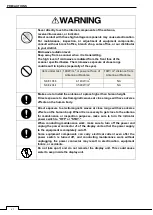
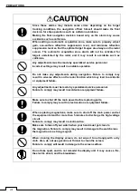
Since these alarms may include some errors depending on the target
tracking conditions, the navigation officer himself should make the final
decision for ship operations such as collision avoidance.
Making the final navigation decision based only on the alarm may cause
accidents such as collisions.
When setting an automatic acquisition zone, make sure to properly adjust
gain, sea-surface reflection suppression level, and rain/snow reflection
suppression level so that the optimal target images are always on the radar
screen. The automatic acquisition zone alarm will not be activated for
targets undetected by the radar, and it may result in accidents such as
collisions.
Any adjustments must be made by specialized service personnel.
Incorrect settings may result in unstable operation.
Do not make any adjustments during navigation. Failure to comply may
result in adverse effects on the radar function which may lead to accidents
or equipment failure.
Any adjustments must be made by specialized service personnel.
Failure to comply may result in accidents or equipment failure.
Make sure to shut off the main power before replacing parts.
Failure to comply may result in electrocution or equipment failure.
When replacing magnetrons, make sure to shut off the main power and let
the equipment stand for more than 5 minutes to discharge the high-voltage
circuit.
Failure to comply may result in electrocution.
Make sure to take off your watch when your hand must get close to
the magnetron. Failure to comply may result in damage to the watch since
the magnetron is a strong magnet.
When cleaning the display screen, do not wipe it too strongly with a dry
cloth. Also, do not use gasoline or thinner to clean the screen.
Failure to comply will result in damage to the screen surface.
Do not take apart, and do not remodel the display unit. It may cause a fire,
the electric shock, and the breakdown.
Содержание SMR-715 series
Страница 1: ...MARINE RADAR EQUIPMENT INSTRUCTION MANUAL...
Страница 2: ......
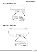
Страница 15: ...xiii EQUIPMENT APPEARANCE NKE 1066 SCANNER UNIT NKE 2044 SCANNER UNIT...
Страница 29: ...Chapter 1 INSTALLATION 3 1 2 3 DIMENSIONAL DRAWING OF DISPLAY MOUNTING...
Страница 30: ...Chapter 1 INSTALLATION 4...
Страница 31: ...Chapter 1 INSTALLATION 5 1 2 4 EXAMPLES OF DISPLAY MOUNTING DESK TOP INSTALLATION Mounting bracket...
Страница 32: ...Chapter 1 INSTALLATION 6 DESKTOP MOUNTING TEMPLATE Note Please note the paper size 182 257...
Страница 34: ...Chapter 1 INSTALLATION 8 FLUSH MOUNTING TEMPLATE Note Please note the paper size 182 257...
Страница 43: ...Chapter 1 INSTALLATION 17 NKE 2044 2FT SCANNER Fig 1 3 6 3 Fig 1 3 6 4...
Страница 47: ...Chapter 1 INSTALLATION 21 Fig 1 4 1 3...
Страница 51: ...Chapter 1 INSTALLATION 25 Fig 1 4 2 3...
Страница 157: ...131 Chapter 10 AFTER SALE SERVICE 10 4 RADAR FAILURE CHECK LIST SMR...
Страница 159: ...133 Chapter 12 SPECIFICATIONS Chapter 12 SPECIFICATIONS...
Страница 160: ...134 Chapter 12 SPECIFICATIONS 12 1 SCANNER DIMENSION 12 1 1 NKE 1066 4 40 RUBBER PLATE...
Страница 161: ...135 Chapter 12 SPECIFICATIONS 12 1 2 NKE 2044...
Страница 162: ...136 Chapter 12 SPECIFICATIONS 12 2 DISPLAY DIMENSION 12 2 1 SMR 715 720...
Страница 163: ...137 Chapter 12 SPECIFICATIONS...
Страница 172: ...APPENDIX A 1 APPENDIX NKE 1066 1 5FT SCANNER INTERCONNECTION DIAGRAM FIG A1...
Страница 173: ...APPENDIX A 2 NKE 2044 2FT SCANNER INTERCONNECTION DIAGRAM FIG A2...
Страница 174: ...APPENDIX A 3 SMR 715 720 DISPLAY UNIT INTER CONNECTION DIAGRAM FIG A3...
Страница 175: ...APPENDIX A 4 SMR 715 720 PRIMARY POWER SUPPLY DIAGRAM FIG A4...
Страница 176: ...APPENDIX A 5 SMR 715 720 INTERCONNECTION DIAGRAM FIG A5...
Страница 177: ...APPENDIX A 6 MEMO...
Страница 187: ...APPENDIX A 16 DECLARATION OF CONFORMITY...
Страница 188: ...APPENDIX A 17...
Страница 189: ...APPENDIX...
Страница 191: ...Chapter 3 ADJUST THE RADAR ECHO A 2...
Страница 192: ...Chapter 3 ADJUST THE RADAR ECHO...


