Chapter 2 START THE BASIC OPERATION
42
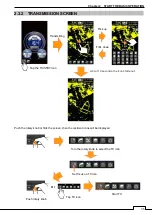
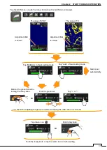
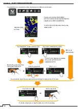
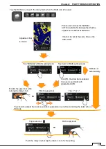
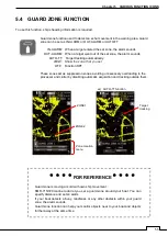
GUARD ZONE setup
Set up the watching area around own-ship.
If a target goes into the set-up area, generate the alarm sound or signal..
On the other hand, if a target goes out the set-up area, generate the alarm sound or signal, too.
One of both is possible to select.
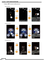
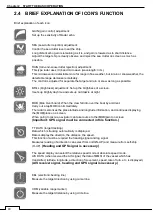
Cursor: A tap is carried out, start, drag and tap off on the target.
The position of this cursor is indicated.
Various kinds of pointing actions uses this cursor..
Tracking of target, AIS data display, setting of guard zone, etc.
MARK: Use when plot a mark on the screen.
Moreover, also when deleting an unnecessary mark, it uses.
(Heading and GPS signal is necessary.)
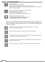
When you want to set the optimum state by situation settings complex radar signal processing function,
try the function that can be easily set by calling a content set in advance settings, the following icon. In
addition, it is also possible to change the radar echo of your choice by changing the adjustment value for
each function after setting.
Mode OFF: Mode function easily sets most appropriate settings in each condition.
Mode OFF sets no specified settings.
Mode Standard: Mode Standard is suitable to monitor relatively short range.
Mode Coast: Mode Coast is suitable to monitor relatively short range, for example, bays and
coasts where many boats and ships are running.
Mode Float: Mode Float is suitable to detect small targets such as fishnets of round netters
hidden by sea clutter returns.
Mode River: Mode River is suitable for using river. This mode reduces sea clutter returns.
Содержание SMR-715 series
Страница 1: ...MARINE RADAR EQUIPMENT INSTRUCTION MANUAL...
Страница 2: ......
Страница 15: ...xiii EQUIPMENT APPEARANCE NKE 1066 SCANNER UNIT NKE 2044 SCANNER UNIT...
Страница 29: ...Chapter 1 INSTALLATION 3 1 2 3 DIMENSIONAL DRAWING OF DISPLAY MOUNTING...
Страница 30: ...Chapter 1 INSTALLATION 4...
Страница 31: ...Chapter 1 INSTALLATION 5 1 2 4 EXAMPLES OF DISPLAY MOUNTING DESK TOP INSTALLATION Mounting bracket...
Страница 32: ...Chapter 1 INSTALLATION 6 DESKTOP MOUNTING TEMPLATE Note Please note the paper size 182 257...
Страница 34: ...Chapter 1 INSTALLATION 8 FLUSH MOUNTING TEMPLATE Note Please note the paper size 182 257...
Страница 43: ...Chapter 1 INSTALLATION 17 NKE 2044 2FT SCANNER Fig 1 3 6 3 Fig 1 3 6 4...
Страница 47: ...Chapter 1 INSTALLATION 21 Fig 1 4 1 3...
Страница 51: ...Chapter 1 INSTALLATION 25 Fig 1 4 2 3...
Страница 157: ...131 Chapter 10 AFTER SALE SERVICE 10 4 RADAR FAILURE CHECK LIST SMR...
Страница 159: ...133 Chapter 12 SPECIFICATIONS Chapter 12 SPECIFICATIONS...
Страница 160: ...134 Chapter 12 SPECIFICATIONS 12 1 SCANNER DIMENSION 12 1 1 NKE 1066 4 40 RUBBER PLATE...
Страница 161: ...135 Chapter 12 SPECIFICATIONS 12 1 2 NKE 2044...
Страница 162: ...136 Chapter 12 SPECIFICATIONS 12 2 DISPLAY DIMENSION 12 2 1 SMR 715 720...
Страница 163: ...137 Chapter 12 SPECIFICATIONS...
Страница 172: ...APPENDIX A 1 APPENDIX NKE 1066 1 5FT SCANNER INTERCONNECTION DIAGRAM FIG A1...
Страница 173: ...APPENDIX A 2 NKE 2044 2FT SCANNER INTERCONNECTION DIAGRAM FIG A2...
Страница 174: ...APPENDIX A 3 SMR 715 720 DISPLAY UNIT INTER CONNECTION DIAGRAM FIG A3...
Страница 175: ...APPENDIX A 4 SMR 715 720 PRIMARY POWER SUPPLY DIAGRAM FIG A4...
Страница 176: ...APPENDIX A 5 SMR 715 720 INTERCONNECTION DIAGRAM FIG A5...
Страница 177: ...APPENDIX A 6 MEMO...
Страница 187: ...APPENDIX A 16 DECLARATION OF CONFORMITY...
Страница 188: ...APPENDIX A 17...
Страница 189: ...APPENDIX...
Страница 191: ...Chapter 3 ADJUST THE RADAR ECHO A 2...
Страница 192: ...Chapter 3 ADJUST THE RADAR ECHO...


