143
Chapter 12 SPECIFICATIONS
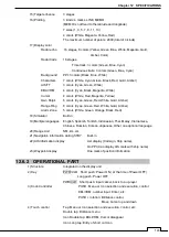
15) Target enhance
3 stages
16) Plotting
3 kinds: 4 marks, LINE, MEMO
(MEMO is not fixed to the latitude and longitude)
7 sizes (1, 3, 5, 7, 9, 11, 13)
4 colors (White, Magenta, Yellow, Red)
The maximum number of points: 2000 (total of 3 kinds)
17) Display color
Radar echo 16 stages, 8 colors (Yellow, Green, Blue, White, Magenta, Gold,
Amber, Color)
Radar trails
16 stages,
Time trails: 3 colors (Green, Blue, Cyan)
Continuous trails: 3 colors (Green, Blue, Cyan)
Background
PPI: 3 colors (Black, Blue, White)
Characters
7 colors (White, Cyan, Green, Black, Red, Gold, Amber)
AIS/TT
3 colors (Cyan, Green, White)
EBL/VRM
4 colors (Cyan, Black, Magenta, White)
Cursor
4 colors (White, Red, Magenta, Yellow)
Own Ship's
6 colors (Cyan, Green, Red, White, Gold, Amber)
Range Ring
6 colors (Cyan, Green, Red, White, Gold, Amber)
Alarm Zone
5 colors (White, Green, Orange, Black, Red)
18) Simulator
Built-in
19) Multiple languages
English, Spanish, Turkish, Indonesian, Thai, Malay, Vietnamese,
Chinese, Russian, Korean, Japanese, Other one optional language
20) Range Unit
NM, km, sm
21) Navigation information during STBY
Built-in
22) AIS information display
List display (Call sign, Ship name),
On PPI (Can display AIS mark with ship name)
23) Waypoint display
One mark of position information
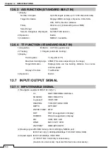
12.6.2 OPERATIONAL PART
1) Structure
Integrated on the display unit
2) Key
PWR/CLR Short push: Power ON ( at the time of Power OFF)
Long push: Power OFF
PWR/CLR Short push: input cancel, back to a up-layer
3) Knob Controller
PUSH : Menu or Icon selection and execution, control
EBL/VRM, number input, Enter, etc.
PUSH + rotation: Brilliance control,
Move Cursor up and down
4) Touch control
Tap: Menu or Icon selection and execution, control, etc.
Double tap: Brilliance menu
Icon Double tap: EBL/VRM, Cursor disappear
Icon Long tap: Entry of short cut Icon
Содержание SMR-715 series
Страница 1: ...MARINE RADAR EQUIPMENT INSTRUCTION MANUAL...
Страница 2: ......
Страница 15: ...xiii EQUIPMENT APPEARANCE NKE 1066 SCANNER UNIT NKE 2044 SCANNER UNIT...
Страница 29: ...Chapter 1 INSTALLATION 3 1 2 3 DIMENSIONAL DRAWING OF DISPLAY MOUNTING...
Страница 30: ...Chapter 1 INSTALLATION 4...
Страница 31: ...Chapter 1 INSTALLATION 5 1 2 4 EXAMPLES OF DISPLAY MOUNTING DESK TOP INSTALLATION Mounting bracket...
Страница 32: ...Chapter 1 INSTALLATION 6 DESKTOP MOUNTING TEMPLATE Note Please note the paper size 182 257...
Страница 34: ...Chapter 1 INSTALLATION 8 FLUSH MOUNTING TEMPLATE Note Please note the paper size 182 257...
Страница 43: ...Chapter 1 INSTALLATION 17 NKE 2044 2FT SCANNER Fig 1 3 6 3 Fig 1 3 6 4...
Страница 47: ...Chapter 1 INSTALLATION 21 Fig 1 4 1 3...
Страница 51: ...Chapter 1 INSTALLATION 25 Fig 1 4 2 3...
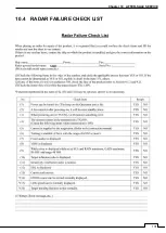
Страница 157: ...131 Chapter 10 AFTER SALE SERVICE 10 4 RADAR FAILURE CHECK LIST SMR...
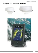
Страница 159: ...133 Chapter 12 SPECIFICATIONS Chapter 12 SPECIFICATIONS...
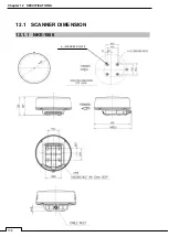
Страница 160: ...134 Chapter 12 SPECIFICATIONS 12 1 SCANNER DIMENSION 12 1 1 NKE 1066 4 40 RUBBER PLATE...
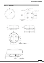
Страница 161: ...135 Chapter 12 SPECIFICATIONS 12 1 2 NKE 2044...
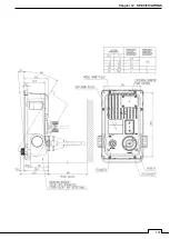
Страница 162: ...136 Chapter 12 SPECIFICATIONS 12 2 DISPLAY DIMENSION 12 2 1 SMR 715 720...
Страница 163: ...137 Chapter 12 SPECIFICATIONS...
Страница 172: ...APPENDIX A 1 APPENDIX NKE 1066 1 5FT SCANNER INTERCONNECTION DIAGRAM FIG A1...
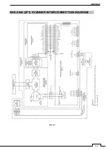
Страница 173: ...APPENDIX A 2 NKE 2044 2FT SCANNER INTERCONNECTION DIAGRAM FIG A2...
Страница 174: ...APPENDIX A 3 SMR 715 720 DISPLAY UNIT INTER CONNECTION DIAGRAM FIG A3...
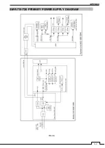
Страница 175: ...APPENDIX A 4 SMR 715 720 PRIMARY POWER SUPPLY DIAGRAM FIG A4...
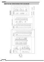
Страница 176: ...APPENDIX A 5 SMR 715 720 INTERCONNECTION DIAGRAM FIG A5...
Страница 177: ...APPENDIX A 6 MEMO...
Страница 187: ...APPENDIX A 16 DECLARATION OF CONFORMITY...
Страница 188: ...APPENDIX A 17...
Страница 189: ...APPENDIX...
Страница 191: ...Chapter 3 ADJUST THE RADAR ECHO A 2...
Страница 192: ...Chapter 3 ADJUST THE RADAR ECHO...

