71
Chapter 5 VARIOUS FUNCTION ICONS
N
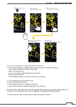
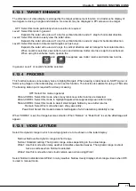
5.12.3 TARGET ENHANCE
The dimension of video display is enlarged by the target enhancement function. And radar echo display of
two targets is closing in angle and distance. As a result, may be displayed in PPI screen as one target.
OFF: Select this mode particularly when resolution is required.
Level1: Select this mode in general.
Expands the radar echo area at 1 step for vertical direction and at 1 step for horizontal direction.
Level2: Select this mode to easily view the radar video.
Expands the radar echo area at 1 step for vertical direction and at 2 steps for horizontal direction.
Level3: Select this mode to detect small targets such as buoys.
Expands the radar echo area at 2 steps for vertical direction and at 3 steps for horizontal direction.
When Level3 is selected, sea clutter returns and rain/snow clutter returns are apt to be enhanced.
When using this enhance mode, operate the
and to suppress sea clutter returns and rain/snow returns.
In general, Level1 or Level2 should be selected.
5.12.4 PROCESS
This function reduces unnecessary noise to highlight targets. When viewing a radar beacon, SART signal, or
fast moving target on the radar display, do not use this function. This function is suitable for using in TM mode.
The bearing data input is required for video processing.
OFF: Select this mode in general.
3Scan-COREL: Select this mode when many rain/snow clutter returns are detected.
4Scan-COREL: Select this mode to highlight targets while suppressing sea clutter returns.
5Scan-COREL: Select this mode to detect small targets hidden by sea clutter returns.
Remain: Select this mode when own ship yaws wildly.
Peak Hold: Select this mode to detect small targets of which detection probability is low.
When “COREL” is set, the image becomes smaller. When “Remain” or “Peak Hold” is set, the afterimage will
appear.
5.12.5 VIDEO LATITUDE
Select the dynamic range in which receiving signals are to be shown on the radar display.
Narrow: Narrows the dynamic range at short range.
Normal: Standard setting. The dynamic range varies depending on the actual range.
Wide1: Use this mode when rainy weather intensifies unwanted waves. The dynamic range is about
twice as wide as when Normal is selected.
Wide2: Use this mode when rain clouds remain even when using Wide1.
Select Normal in standard and Wide1 in rainy weather. Narrow clearly displays short-range videos when STC
is used in manual mode.
Содержание SMR-715 series
Страница 1: ...MARINE RADAR EQUIPMENT INSTRUCTION MANUAL...
Страница 2: ......
Страница 15: ...xiii EQUIPMENT APPEARANCE NKE 1066 SCANNER UNIT NKE 2044 SCANNER UNIT...
Страница 29: ...Chapter 1 INSTALLATION 3 1 2 3 DIMENSIONAL DRAWING OF DISPLAY MOUNTING...
Страница 30: ...Chapter 1 INSTALLATION 4...
Страница 31: ...Chapter 1 INSTALLATION 5 1 2 4 EXAMPLES OF DISPLAY MOUNTING DESK TOP INSTALLATION Mounting bracket...
Страница 32: ...Chapter 1 INSTALLATION 6 DESKTOP MOUNTING TEMPLATE Note Please note the paper size 182 257...
Страница 34: ...Chapter 1 INSTALLATION 8 FLUSH MOUNTING TEMPLATE Note Please note the paper size 182 257...
Страница 43: ...Chapter 1 INSTALLATION 17 NKE 2044 2FT SCANNER Fig 1 3 6 3 Fig 1 3 6 4...
Страница 47: ...Chapter 1 INSTALLATION 21 Fig 1 4 1 3...
Страница 51: ...Chapter 1 INSTALLATION 25 Fig 1 4 2 3...
Страница 157: ...131 Chapter 10 AFTER SALE SERVICE 10 4 RADAR FAILURE CHECK LIST SMR...
Страница 159: ...133 Chapter 12 SPECIFICATIONS Chapter 12 SPECIFICATIONS...
Страница 160: ...134 Chapter 12 SPECIFICATIONS 12 1 SCANNER DIMENSION 12 1 1 NKE 1066 4 40 RUBBER PLATE...
Страница 161: ...135 Chapter 12 SPECIFICATIONS 12 1 2 NKE 2044...
Страница 162: ...136 Chapter 12 SPECIFICATIONS 12 2 DISPLAY DIMENSION 12 2 1 SMR 715 720...
Страница 163: ...137 Chapter 12 SPECIFICATIONS...
Страница 172: ...APPENDIX A 1 APPENDIX NKE 1066 1 5FT SCANNER INTERCONNECTION DIAGRAM FIG A1...
Страница 173: ...APPENDIX A 2 NKE 2044 2FT SCANNER INTERCONNECTION DIAGRAM FIG A2...
Страница 174: ...APPENDIX A 3 SMR 715 720 DISPLAY UNIT INTER CONNECTION DIAGRAM FIG A3...
Страница 175: ...APPENDIX A 4 SMR 715 720 PRIMARY POWER SUPPLY DIAGRAM FIG A4...
Страница 176: ...APPENDIX A 5 SMR 715 720 INTERCONNECTION DIAGRAM FIG A5...
Страница 177: ...APPENDIX A 6 MEMO...
Страница 187: ...APPENDIX A 16 DECLARATION OF CONFORMITY...
Страница 188: ...APPENDIX A 17...
Страница 189: ...APPENDIX...
Страница 191: ...Chapter 3 ADJUST THE RADAR ECHO A 2...
Страница 192: ...Chapter 3 ADJUST THE RADAR ECHO...


