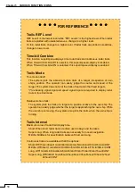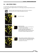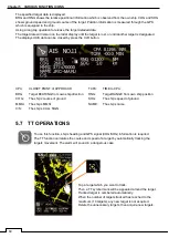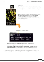
54
Chapter 5 VARIOUS FUNCTION ICONS
5.3 CURSOR FUNCTION
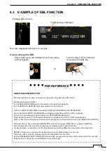
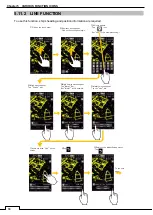
Adjust the cursor position
The cursor elimination method
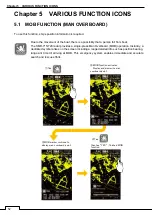
Using the cursor function can read out a selected target information.
Tap the cursor icon. Tap anywhere on the screen, the cursor mark is
displayed in place where it has been tapped. At the same time, the range and
bearing information at that point are displayed in the lower side of the screen.
If the GPS signal is coming in, the latitude and longitude information of that
point are also can be displayed.
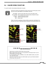
Tap anywhere on the screen
“BEARING”
BRG 20.0°
“RANGE”
RNG 0.3464NM
“TTG”
TTG +2.1MIN
In case of GPS signal coming in
“Latitude “ LAT 35° 04.2292’N
“Longitude” LON 136° 46.3008’E
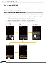
Do not touch the screen for about 10 seconds,
the information bar will be fade out.
The cursor icon is eliminable by carrying out a
double tap.
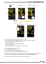
You can use the rotary knob to adjust the cursor position.
Horizontal direction: Turn the rotary knob.
・
Turn to the right. Then the cursor move to right.
・
Turn to the left. Then the cursor move to left.
Vertical direction: Turning while pressing the rotary knob.
・
Turn to the right. Then the cursor move to upward.
・
Turn to the left. Then the cursor move to downward.
Содержание SMR-715 series
Страница 1: ...MARINE RADAR EQUIPMENT INSTRUCTION MANUAL...
Страница 2: ......
Страница 15: ...xiii EQUIPMENT APPEARANCE NKE 1066 SCANNER UNIT NKE 2044 SCANNER UNIT...
Страница 29: ...Chapter 1 INSTALLATION 3 1 2 3 DIMENSIONAL DRAWING OF DISPLAY MOUNTING...
Страница 30: ...Chapter 1 INSTALLATION 4...
Страница 31: ...Chapter 1 INSTALLATION 5 1 2 4 EXAMPLES OF DISPLAY MOUNTING DESK TOP INSTALLATION Mounting bracket...
Страница 32: ...Chapter 1 INSTALLATION 6 DESKTOP MOUNTING TEMPLATE Note Please note the paper size 182 257...
Страница 34: ...Chapter 1 INSTALLATION 8 FLUSH MOUNTING TEMPLATE Note Please note the paper size 182 257...
Страница 43: ...Chapter 1 INSTALLATION 17 NKE 2044 2FT SCANNER Fig 1 3 6 3 Fig 1 3 6 4...
Страница 47: ...Chapter 1 INSTALLATION 21 Fig 1 4 1 3...
Страница 51: ...Chapter 1 INSTALLATION 25 Fig 1 4 2 3...
Страница 157: ...131 Chapter 10 AFTER SALE SERVICE 10 4 RADAR FAILURE CHECK LIST SMR...
Страница 159: ...133 Chapter 12 SPECIFICATIONS Chapter 12 SPECIFICATIONS...
Страница 160: ...134 Chapter 12 SPECIFICATIONS 12 1 SCANNER DIMENSION 12 1 1 NKE 1066 4 40 RUBBER PLATE...
Страница 161: ...135 Chapter 12 SPECIFICATIONS 12 1 2 NKE 2044...
Страница 162: ...136 Chapter 12 SPECIFICATIONS 12 2 DISPLAY DIMENSION 12 2 1 SMR 715 720...
Страница 163: ...137 Chapter 12 SPECIFICATIONS...
Страница 172: ...APPENDIX A 1 APPENDIX NKE 1066 1 5FT SCANNER INTERCONNECTION DIAGRAM FIG A1...
Страница 173: ...APPENDIX A 2 NKE 2044 2FT SCANNER INTERCONNECTION DIAGRAM FIG A2...
Страница 174: ...APPENDIX A 3 SMR 715 720 DISPLAY UNIT INTER CONNECTION DIAGRAM FIG A3...
Страница 175: ...APPENDIX A 4 SMR 715 720 PRIMARY POWER SUPPLY DIAGRAM FIG A4...
Страница 176: ...APPENDIX A 5 SMR 715 720 INTERCONNECTION DIAGRAM FIG A5...
Страница 177: ...APPENDIX A 6 MEMO...
Страница 187: ...APPENDIX A 16 DECLARATION OF CONFORMITY...
Страница 188: ...APPENDIX A 17...
Страница 189: ...APPENDIX...
Страница 191: ...Chapter 3 ADJUST THE RADAR ECHO A 2...
Страница 192: ...Chapter 3 ADJUST THE RADAR ECHO...

