4. Troubleshooting
•
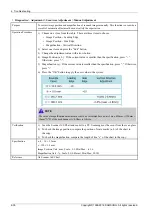
Diagnostics > Adjustment > Print Adjustment > Image Position
Purpose
To correct image position of print-outs manually.
Operation Procedure
1) Select a tray required adjustment.
2) Change the adjustment value with arrow button. “+” value will move to Tail-Edge while
“-” value will move to Lead-Edge.
E
xa mple
Ca se s
Simple x
Le a ding
Edge
Simple x
Side Edge
Duple x
Le a ding
Edge
Duple x
Side Edge
= 8.5 mm
+ 15
= 11.6 mm
-16
¡¡
= 8.0 mm
+ 20
¢¢
= 13.0 mm
-30
Verification
Print out and check if all the position of scale marks (,,,) in the image are located within the specified
limit.
Specification
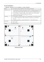
a, b, e, f : 10 mm, ± 1.5 mm
Reference
Scanner A/S Chart
Copy Adjustment
•
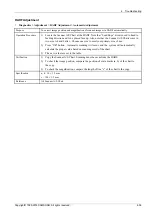
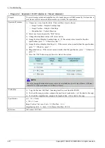
Diagnostics > Adjustment > Copy Adjustment > Image Position
Purpose
To correct image position of copied images manually.
Operation Procedure
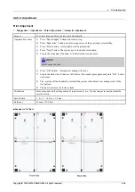
1) Select a tray required adjustment.
2) Change the adjustment value with arrow button. “+” value will move to Tail-Edge while
“-” value will move to Lead-Edge.
E
xa mple
Ca se s
Simple x
Le a ding
Edge
Simple x
Side
Edge
Simple x
Le a ding
Edge
Simple x
Side
Edge
= 11.5 mm
-15
= 8.4 mm
-
16
¡¡
= 12.0 mm
-20
¢¢
= 7.0 mm
+ 30
Verification
1) Copy the Scanner A/S Chart . Scanning must be occur at the scanner glass .
2) Check if all the position of scale marks (a, b, e, f) in the image are located within the
specified limit.
Specification
a, b, e, f : 10 mm ± 1.5 mm
Reference
Scanner A/S Chart
4-33
Copyright© 1995-2016 SAMSUNG. All rights reserved.
Содержание CLX-9251 Series
Страница 122: ...2 Product Specifications and Description 2 108 Copyright 1995 2016 SAMSUNG All rights reserved ...
Страница 167: ...3 Disassembly and Reassembly 7 Remove the Cover Side F Copyright 1995 2016 SAMSUNG All rights reserved 3 45 ...
Страница 454: ...4 Troubleshooting 4 269 Copyright 1995 2016 SAMSUNG All rights reserved ...

