R5
SUPREME - Navigation System
INSTALLATION
7000 118-301, A3
Page 35
2.8.2.3
User Port 2
The port can only be used to output data from the R5 SUPREME Navigation System
to external equipment. The TX signals of the port shall be connected to the RX
signals of the external equipment.
It is up to the user to configure the types of messages that shall be sent on the port,
as well as the baud rate used for communication.
If an R4 DGPS Navigational Sensor is used this port can also be used to output
differential corrections in RTCM SC-104 format.
2.8.2.4
Alarm Out Binary Port
The Alarm Out binary port is used to indicate navigational alarms to external alarm
signalling and alarm monitoring systems. The Alarm Out wire should be connected
via an alarm relay unit to negative supply. The port is normally active supplying
power. When an alarm is activated, the port will go low and supply 0 VDC. The port
will remain low until the alarm is deactivated. Once the alarm is deactivated the port
will go high, supplying power again.
If the R5 NAV Junction box is installed, this signal will be connected to the Junction
box internal alarm relay.
2.8.2.5
Alarm Acknowledge Binary Port
The Alarm Acknowledge binary port is used to acknowledge
all
active alarms. The
Alarm Ack In signal should be connected to Alarm Ack GND via a normally open
momentary switch. The switch should be closed to activate the Alarm Acknowledge
signal and acknowledge the active alarms.
2.8.2.6
Speed Log Out Port
To use the port, the Speed Log Out signal should be connected via a pulse counting
circuit to Signal ground.
The number of pulses that can be generated per nautical mile can range between
100 and 400, configured as described in the section 4.2.12
―Port Rates‖. The default
setting is that Speed Log output is disabled.
Содержание R5 SUPREME AIS
Страница 1: ...OPERATION INSTALLATION MANUAL Saab TransponderTech R5 SUPREME Navigation System ...
Страница 2: ...This page is intentionally empty ...
Страница 60: ...R5 SUPREME Navigation System OPERATION 7000 118 301 A3 Page 60 5 4 System Menus Tree View ...
Страница 103: ...R5 SUPREME Navigation System OPERATION 7000 118 301 A Page 103 Figure 92 Update Software ...
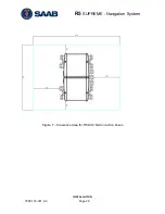
Страница 151: ...R5 SUPREME Navigation System MECHANICAL DRAWINGS 7000 118 301 A Page 151 14 2 CDU Panel Mount Cutout Hole dimensions ...


