R5
SUPREME - Navigation System
INSTALLATION
7000 118-301, A3
Page 31
2.6.2
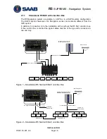
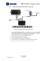
System interconnection with R5 NAV Junction Box
User
Port 1
Speed
Log
Alarm
Relay
User
Port 4
User
Port 3
User
Port 2
Alarm
ACK
R4 GPS Navigation Sensor or
R4 DGPS Navigation Sensor
(D)GPS Antenna
R5 NAV
Junction Box
4
GP I/O
R5 NAV Sensor Cable
External power 24 VDC
R5 Signal Cable
R5 Power Cable
Figure 8
– Installation with R5 NAV Junction Box
1. Connect the R5 SUPREME CDU to the junction box by using the R5 Signal
Cable, DSUB-DSUB and the R5 Power Cable, Connect the R4 Navigation
Sensor to the junction box by using the R5 NAV Sensor Cable.
2. Connect the GPS antenna to the R4 Navigation Sensor.
3. Connect Alarm Relay signal to bridge alarm.
4. Connect additional external sensors and equipment.
5. Connect the R5 NAV Junction Box to an external 24 VDC power source.
NOTE: see section 2.3
“Installation Cables” for cable specifications.
Содержание R5 SUPREME AIS
Страница 1: ...OPERATION INSTALLATION MANUAL Saab TransponderTech R5 SUPREME Navigation System ...
Страница 2: ...This page is intentionally empty ...
Страница 60: ...R5 SUPREME Navigation System OPERATION 7000 118 301 A3 Page 60 5 4 System Menus Tree View ...
Страница 103: ...R5 SUPREME Navigation System OPERATION 7000 118 301 A Page 103 Figure 92 Update Software ...
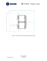
Страница 151: ...R5 SUPREME Navigation System MECHANICAL DRAWINGS 7000 118 301 A Page 151 14 2 CDU Panel Mount Cutout Hole dimensions ...


