Configuration Registers
Publication PUB091-003-00_0119
57 of 76
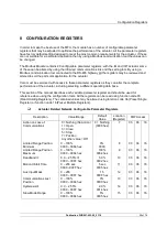
8.1 Actuator Related Configurable Parameter Registers
These parameter registers set up the response of the actuator will take to various control and network
actions.
8.1.1
Action on Loss of Communications (Register 7)
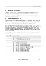
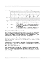
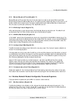
This register is used in conjunction with register 13 (Communications Lost Position) and 21
(Communications Fault Timer).
The Action on Loss of Communications register defines the actuator action that will result after the
time set for the Communications Fault Timer (register 21) if there is no network communication activity
detected by the MFU.
The action may be
Nothing
(0)
No action, actuator will complete any command in process (the default
setting)
Open
(1)
The actuator will open the valve
Close
(3)
The actuator will close the valve
Stop
(5)
The actuator stops
Position
(7)
The actuator will adjust the valve position to the setting given in the
Communications Lost Position (register 13).
8.1.2
Limited Range Position Minimum and Maximum (Registers 8 and 9)
These parameter registers are used to define the positions in the range of valve travel that will be
reported as 0 to 100% if it the whole travel from the closed position to the open position is not used. In
addition, the position demand setpoint output value will also be modified to follow this limited range.
It is possible to make the position data reported and the position controller relate to a reduced span of
actual valve travel. In this mode the position data relates to the reduced portion of the valve stroke.
This is sometimes used where the valve is required to have a 0% position (or 100% position) that is
not the same as the fully closed position (or fully open position). These parameters define the actual
limited range of valve travel that will be used for the position reporting and control by the positioner.
Note that the digital open and close commands will still make the valve travel over its full stroke. The
special case analogue commands of 0% and 100% that would otherwise cause the actuator to travel
to the limit switch or torque off positions are inhibited if values other than 0 and 100 are set in these
parameters.
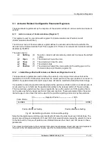
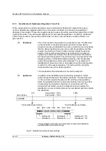
The values inserted relate to the maximum total valve travel between closed and open and represent
the point in the full stroke which will now be used for the limited stroke 0 and 100 values.
0% ----------------- Reported Position --------------------- 100%
Valve Stroke
CLOSED
OPEN
Position Minimum Setting
Position Maximum Setting
Fig 26: Limited Range Position Control and Reporting

