background image


 Modbus Data Base


Publication PUB091-003-00_0119


45 of 76 


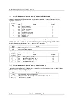
Code 05 and 15 - Force Single Coil or Multiple Coils 


The output coils are the discrete outputs from the actuator or its digital 
control commands. Code 05 writes one coil per message whilst code 
15 can write values to several at once. 


Code 06 and 16 - Preset Single Register or Multiple Registers 


Registers are used for position control and also for digital control and 
can be accessed singly, or in multiples with these codes. Function 
code 06 writes a single 16 bit register whilst function code 16 can 
write several in one transaction. 


Code 07 – Read Exception Status


This is a specific short message function code which returns 
predetermined discrete data from the MFU. The message is used to 
allow fast transfer of a small data packet. 


Code 08 - Loopback Diagnostic Test 


The purpose of the Loopback Test is to test the communication 
system between the Modbus Module and the host. The MFU supports 
this test when used with diagnostic code 00, Return Query Data, and 
02, Return Diagnostic Register. No other diagnostic test codes are 
supported. 


Function Code 17 – Report Slave ID


This function code generates a response that contains specific 
information about the MFU and actuator (providing the data has been 
entered on setup). 


Exception Response Codes


Error code 01 will be presented back to the host if the function code in 
the data message is not one of those supported by the Modbus 
Module or the message length is not as expected. 
 
Error code 02 will be presented back to the host if the Data Address is 
not valid for the Modbus Module.  
 
Error code 03 will be presented back to the host if the value to be 
written in a coil or register write is not valid for the register or coil 
location chosen in the MFU. 
 
Error code 6 will be presented back to the host if the MFU is unable to 
respond with a correct message because it is busy.  


Содержание Modbus EH Pro

Страница 1: ...Publication PUB091 003 00_0119 Modbus RTU Actuator Control Mk2 Option Card Technical Manual IQ Pro IQT Pro SI Pro EH Pro ROMpak and Q...

Страница 2: ...anges of actuators there will be different numbers of valid inputs and outputs for each range depending on the actuator capabilities For example actuators not fitted with a battery cannot report Batte...

Страница 3: ...5 1 Single Highway with Analogue Input 22 4 5 2 Dual Highway 23 4 5 3 Single Highway with Internal Repeater 24 5 THE ACTUATOR INPUT AND OUTPUT SIGNALS 27 5 1 Control Outputs 27 5 1 1 Controls Priorit...

Страница 4: ...igurable Parameter Registers 57 8 1 1 Action on Loss of Communications Register 7 57 8 1 2 Limited Range Position Minimum and Maximum Registers 8 and 9 57 8 1 3 Deadband and Hysteresis Registers 10 an...

Страница 5: ...10 Fig 8 The MFU module profiled for the Q actuator 13 Fig 9 The MFU located in a ROMpak actuator 14 Fig 11 Typical RS 485 Data Highway 17 Fig 12 RS 485 Data Highway Topology 18 Fig 13 Typical RS 485...

Страница 6: ...ble from the Rotork module Node A single device on the fieldbus RS 485 The electrical properties of the data highway as defined by the IEC standard copper conductors 2 wire twisted pair Segment A sect...

Страница 7: ...us master tool or via the Infra red setting tools for the IQ Pro IQT Pro SI Pro and EH Pro products If the data highway speed was not specified at time of order or it is changed it may be necessary to...

Страница 8: ...ed RS 485 highways Single RS 485 highway with inbuilt isolating repeater Communication Medium RS4 85 2 wire highway single or dual half duplex Protocol Modbus RTU Mode Master Slave module is a slave F...

Страница 9: ...ator electrical housing IQ Pro IQT Pro SI Pro EH Pro and Q All the connectors are polarised to prevent incorrect insertion Network Interface Card NIC This small printed circuit board carries the Modbu...

Страница 10: ...ing this data to the Network Interface card For the IQ Pro and IQT Pro it is used simply for physical connection to the main card The primary connection to the actuator circuits is by a multi pin conn...

Страница 11: ...Interface Card of the actuator The MFU does not sit in the main control path for the actuator and does not affect the actuator control integrity The Modbus RS 485 fieldbus data highway connections are...

Страница 12: ...Main pcb Fig 7 The IQ Pro and IQT Pro MFU and its location in an IQ Pro or IQT Pro actuator With the IQ Pro and IQT Pro actuators the remote inputs are always present they are conditioned by the MFU a...

Страница 13: ...control inputs as Digital Inputs The following table shows the wiring harnesses that must be fitted and the function of each loom for the Q range actuator MFU Socket Wiring Harness SK2 24V power suppl...

Страница 14: ...side the ROMpak electrical housing Fig 9 The MFU located in a ROMpak actuator SK3 is the connection to the Modbus Fieldbus Data Highway this is connected to SK23 on the main PCB assembly via an intern...

Страница 15: ...Fig 10 The MFU and its location in an SI Pro or EH Pro actuator With the SI Pro and EH Pro actuators the remote inputs are always present they are conditioned by the MFU and there is an option to inc...

Страница 16: ...ts main connector Once removed from the main connector the wiring loom connectors should be removed The replacement board is fitted in the reverse order to removal The wiring harnesses are polarised s...

Страница 17: ...to the maximum addressable of 247 then RS 485 repeaters may be added after each group of 32 The standard default address used by the Modbus Module is 247 The length of the highway will determine the m...

Страница 18: ...h spur and the cumulative total are dependent on the system speed in use The table below suggests the maximum figures for cable type A also defined below The segment length is the total of the trunk a...

Страница 19: ...n Information on Belden cable may be found on the Belden web site www belden com or at http bwcecom belden com where a search on RS 485 will reveal technical papers and cable information Belden Part N...

Страница 20: ...inimise this requirement the actuator transceiver chips include secure turn round components For IQ IQT SI EH and Q actuators that use the MFU there is a termination resistor inside each actuator One...

Страница 21: ...is an analogue transmitter connected it will also return the value from the transmitter signal The dual channel version is used for redundant highway applications where the highway integrity is impor...

Страница 22: ...B terminals on the other Data line 1A is positive with respect to data line 1B when the MFU is transmitting a 1 If an analogue input is being used it is connected to the analogue input terminals The M...

Страница 23: ...umper Settings for Dual Highway Option Or LK5 LK6 not fitted LK6 LK5 SK5 SK7 SK10 EPROM SK1 SK2 SK8 SK3 SK3 LK10 9 8 7 4 3 2 1 Terminator 1 1A 1B c Common 1 Actuator c Terminator 2 2A 2B Common 2 RS48...

Страница 24: ...el mode they must be positioned as shown in the diagram LK5 and LK6 may in some cases not be fitted This is also correct 4 5 3 Single Highway with Internal Repeater With this option a single highway p...

Страница 25: ...eft Top Top Left Right Left Right 19 200 38 400 Left Left Left Left Top Top Right Left Right Left 57 600 115 200 Left Left Left Left Top Top Right Right Right Right Fig 19 Single Highway with Internal...

Страница 26: ...Modbus MFU Option Card Installation Manual 26 of 76 Publication PUB091 003 00_0119 Fig 20 Jumper Settings for Single Highway with Internal Repeater Option...

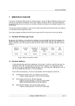
Страница 27: ...the MFU The IQ Pro will be similar to the IQT Pro and the ROMpak will be similar to the Q 5 1 Control Outputs The Modbus Module can be used to control the actuator and position the valve The valve may...

Страница 28: ...actuator provided Local Local Stop Remote selector is in Remote On IQ or IQT actuators Modbus commands are not inhibited by the Inhibit DI 4 input parameter setting and DI 4 condition No interlock is...

Страница 29: ...k To initiate Analogue Position Control a value must be written the Position DV register range 0 100 0 resolution 0 1 The valve will open to the appropriate amount and stop in that position within the...

Страница 30: ...s applied whilst Hard Wired Stop is present stop is cancelled Fig 22 IQ IQT and SI EH Controls Priorities In the case of the Q actuator the control selection is slightly different because the actuator...

Страница 31: ...or This is because a network ESD command overrides the actuator local controls In order to remove the ESD action it is necessary to write a new command and if the actuator has local selected then the...

Страница 32: ...rol Disable feature It is possible to set the IQ or IQT ESD DI 4 input so that the IQ IQT actuator ignores open stop close ESD and position control signals sent over the Modbus network If the ESD DI 4...

Страница 33: ...ator position is changing due to the motor running or in the case of the IQ or IQT if the output drive is moving this bit will be set true 1 Close Limit This data bit indicates that the actuator has r...

Страница 34: ...stat trips Only once the motor has cooled down and the thermostat has reset itself can a new Remote Host or Local command to move the actuator be carried out A setting on the actuator main board allow...

Страница 35: ...ceeding its prescribed number of starts per hour or to reduce the effects of hunting during closed loop control The Interrupter Timer in the IQ IQT can be used over part or the entire actuator stroke...

Страница 36: ...t the actuator from closing Digital Input DI 1 Applicable to IQ and IQT actuators only This bit reports the status of the contact connected to the actuator hard wired Open terminals The input can be u...

Страница 37: ...accuracy to be achieved without overshoot The deviation from the setpoint at which slow mode is adopted is set in the associated parameter When slow mode is in use this bit will be true 1 The IQ and Q...

Страница 38: ...selector is in the Remote position Close Torque Set One register records the actuator setting for the maximum generated torque value permitted when the actuator is moving towards the closed position...

Страница 39: ...Input and Output Signals Publication PUB091 003 00_0119 39 of 76 operated The first register contains the low order 16 bits The counter cannot be reset to zero...

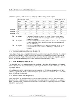
Страница 40: ...y s NA NA NA 3 5 3 5 3 5 3 5 3 5 3 5 3 5 Note In the Single Highway with Internal Repeater Modbus Module option there is a propagation delay in the repeater NA not applicable the repeater function can...

Страница 41: ...communication speed and format Both the communications ports share one set of common values for these parameters When communication is active every device on the highway reads all the data request or...

Страница 42: ......

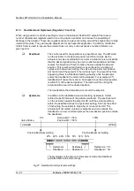
Страница 43: ...ame completion then the next byte received will be the start of a new message and begin with the address Modbus Address Function Code Register or Discrete Address Number of Registers or Bits Data Fiel...

Страница 44: ...legal data address Register or discrete address invalid 03 Illegal data value 06 Busy To read data the function code to use will depend on whether the data is to be read as single bits or as 16 bit re...

Страница 45: ...the Loopback Test is to test the communication system between the Modbus Module and the host The MFU supports this test when used with diagnostic code 00 Return Query Data and 02 Return Diagnostic Reg...

Страница 46: ...s so far as the user is concerned In such cases the address programmed into the host would be different to those listed All data locations listed start from 0 Please check the host system documentatio...

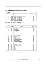
Страница 47: ...sed with Function Code 02 Read Discrete Inputs Location Bit R W Data Range 0 RO Actuator moving 0 1 1 RO Closed limit 0 1 2 RO Open limit 0 1 3 RO Running closed 0 1 4 RO Running open 0 1 5 RO Remote...

Страница 48: ...RO Thermostat tripped 0 1 0 9 RO Monitor relay 0 1 0 10 RO Valve obstructed 0 1 0 11 RO Valve jammed 0 1 0 12 RO Valve moving by hand 0 1 0 13 RO Moving inhibited 0 1 0 14 RO Position control enabled...

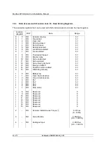
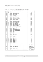
Страница 49: ...n 0 78 hex 37 RO Torque at 30 open direction 0 78 hex 38 RO Torque at 40 open direction 0 78 hex 39 RO Torque at 50 open direction 0 78 hex 40 RO Torque at 60 open direction 0 78 hex 41 RO Torque at 7...

Страница 50: ...0 10 RO Valve obstructed 0 1 0 11 RO Valve jammed 0 1 0 12 RO Valve moving by hand 0 1 0 13 RO Moving inhibited 0 1 0 14 RO Position control enabled 0 1 0 15 RO Watchdog recovery 0 1 1 0 RO Battery l...

Страница 51: ...1 to turn on the command and 0 to turn off the command The commands to open close stop or ESD the actuator are not cancelled by writing a 0 The actuator latches the instruction and will complete the a...

Страница 52: ...st The Loopback Test is used to test communications only In a correctly working unit the return message is the same as the query sent Two codes are supported Code Data 00 Return query data 02 Return d...

Страница 53: ...ut 02 03 04 Watchdog 0 15 Digital Input 02 03 04 Battery low 1 16 Digital Input 02 03 04 Open Interlock input active 1 17 Digital Input 02 03 04 Close Interlock input active 1 18 Digital Input 02 03 0...

Страница 54: ...tion code 01 02 03 04 05 06 15 16 Other Database format 25 Parameter reg 03 06 16 Actuator Tag number 26 31 Parameter reg 03 06 16 Data logger data 32 59 Input register 03 Memory status OK Fault 0 Dia...

Страница 55: ...ncluding selecting a different operating data base This section of the manual describes each variable parameter register and should be used for reference when using the configuration tools All the reg...

Страница 56: ...eater than the deadband causes the hysteresis to be set to 0 1 IQ Setting tool only allows 0 0 to 9 9 deadband to be set Modbus Network Related Network Configurable Parameter Registers Description Val...

Страница 57: ...t the whole travel from the closed position to the open position is not used In addition the position demand setpoint output value will also be modified to follow this limited range It is possible to...

Страница 58: ...valve and actuator combination will hunt around the setpoint if the inertia is high To prevent this from happening there is a Deadband setting whereby once the actuator enters the deadband the motor...

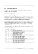
Страница 59: ...8 bits Each bit in the high order nibble x7 x6 x5 x4 either enables or disables the associated input for control of the actuator The bits in the low order nibble y3 y2 y1 y0 determines if the input re...

Страница 60: ...etting in this parameter register determines the position in the range 0 to 100 that the actuator will move to if the Modbus network communications stops being received provided the Fault Mode Registe...

Страница 61: ...bration to ensure it is accurately reported This parameter can only be set when the MFU is on line and the analogue input should be connected to a calibration source When the register is set this caus...

Страница 62: ...l the actuator power is cycled On a dual channel unit both channels operate using the same data base The Mk2 data base is as detailed in Section 7 Where the MFU is being used as a spare part to replac...

Страница 63: ...tion port for setting the actuator performance limit switches and so on This communication link can be used to set some but not all of the MFU parameter registers The registers should still be checked...

Страница 64: ...ocal control 2 wire control External interlocks Conditional control OE OI OF Od OP OJ Or OS Extra indication contacts CPT Folomatic remote control must be ON Remote control source must be set to OP Bu...

Страница 65: ...l source must be set to OP rP Remote Priority EA EO Ec rE Et PP SP ESD action ESD Local Stop Override ESD contact type ESD Manual Reset ESD Temp Signal Loss Partial Stroke Position Set up Partial Stro...

Страница 66: ...registers The table lists all the registers that must be checked and set up for each Modbus Module on a network The data should be recorded for each module Actuator Configurable Registers Parameter N...

Страница 67: ...MFU fitted or the MFU may be damaged If the network is attached to the correct terminals and there are no communications then perhaps the A and B connections are reversed These could be swapped again...

Страница 68: ......

Страница 69: ...e from the Mk2 is in the data base for collecting data and issuing commands The electrical and physical properties remain as the same This section describes the Mk1 data base 12 2 Input and Output Sig...

Страница 70: ...tor open contactor energised Interrupter Timer Interrupter Timer operating MIT Active Motion Inhibit Timer active Open Interlock input Open Interlock present Close Interlock input Close Interlock pres...

Страница 71: ...ghway plus analogue input Dual highway one common address and baud rate Single highway with repeater 12 4 Modbus Data Base Message format RTU Modbus Address 1 to 247 Dual channel version both channels...

Страница 72: ...us Function code 02 Location Bit R W Data Range 0 RO Actuator moving 0 1 1 RO Closed limit 0 1 2 RO Open limit 0 1 3 RO Thermostat Tripped 0 1 4 RO Monitor Relay 0 1 5 RO Local selected 0 1 6 RO Remot...

Страница 73: ...mum position 0 FFFF 0 100 5 R W Maximum position 0 FFFF 0 100 6 R W Data Base Format power must be cycled for change to take effect 0 1 0 Mk1 data 1 Mk2 data Read Input Registers Function code 04 Loca...

Страница 74: ...served 10 Reserved 11 Reserved 12 RS 485 highway ESD active 13 Auxiliary control input active 14 Positioner MIT active 15 Positioner enable flag Bits 0 to 7 generate the error bit in the digital statu...

Страница 75: ...12 5 Configuration The module should be placed into Mk2 mode to set up all the configurable registers Once these are set the mode can be returned to Mk1 for use on the Mk1 network The complete list o...

Страница 76: ...ork com Rotork reserves the right to amend and change specifications without prior notice Published data may be subject to change UK Rotork PLC Tel 44 0 1225 733 200 Fax 44 0 1225 333 467 e mail mail...

Отзывы: