Modbus MFU Option Card Installation Manual
56 of 76
Publication PUB091-003-00_0119
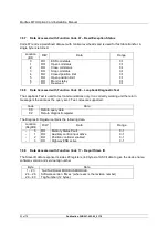
Description
Value/Range
Default
Value
Location
(Register)
R/W Access
Valve Jammed Time
0 – 255 sec
0000 – 00FF hex
5 sec
0005 hex
16
03
06
16
Manual Movement Travel
0 – 100%
0000 – 0064 hex
10%
000A hex
17
03
06
16
Watchdog Timeout
0 – 255 sec
0000 – 00FF hex
10 sec
000A hex
18
03
06
16
ESD DI-4/Net Disable
DI-4 is ESD = 0
DI-4 is Net Disable = 1
ESD
0000 hex
19
03
06
16
Analogue Input Max
0 – 1023
0000 – 3FF hex
0
0000 hex
20
03
06
16
Communications Fault
Timer
0 – 255 sec
0000 – 00FF hex
10 sec
000A hex
21
03
06
16
Note:
- Setting the
deadband lower than the hysteresis, or the hysteresis greater than the
deadband causes the hysteresis to be set to 0.1%
-
IQ Setting tool only allows 0.0 to 9.9% deadband to be set
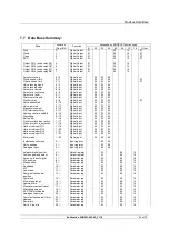
Modbus Network Related Network Configurable Parameter Registers
Description
Value/Range
Default
Value
Location
(Register)
R/W Access
Modbus Address
1 – 247
0001 – 00F7 hex
247
00F7 hex
22
03
06
16
Baud Rate (baud)
0 = not used
1 = 300
6 = 9k6
2 = 600
7 = 19k2
3 = 1k2
8 = 38k4
4 = 2k4
9 = 57k6
5 = 4k8
A = 115k2
(values in hex)
9k6
(0006 hex)
23
03
06
16
Parity/Stop bits
0 = No parity, 1 stop bit
1 = No parity, 2 stop bits
2 = Even, 1 stop bit
3 = Even, 2 stop bits
4 = Odd, 1 stop bit
5 = Odd, 2 stop bits
None/1
(0000 hex)
24
03
06
16
Data Base Format
Modbus Mk1/Mk2
0 = Mk1
1 = Mk2
Mk2
(0001)
25
03
06
16
Actuator Tag Name
Any ASCII char
(12 characters max)
(blank)
all = 0000
26 to 31
03
06
16
Note:
- When altered, the new value will only take effect after the actuator power has been
cycled.


