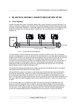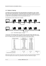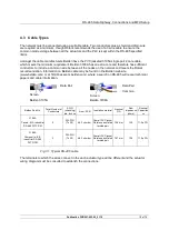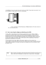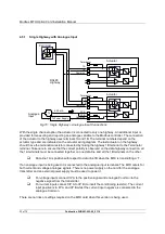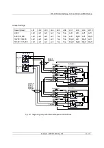
RS-485 Data Highway, Connections and MFU Setup
Publication PUB091-003-00_0119
13 of 76
3.2 Inside a Q actuator
The MFU is fitted in the option board position in this actuator. Only one option board may be fitted at
any one time. The necessary internal components must also be present; in this case a potentiometer
and auxiliary limit switches at end of travel must be fitted to the actuator.
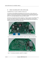
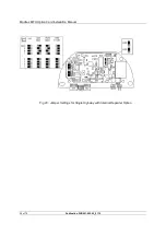
The illustration (Fig 8) shows the Q version of the circuit board.
Digital Outputs from relay contacts are not supported from the Q actuator, nor is the ability to report
the status of the remote control inputs as Digital Inputs. The following table shows the wiring
harnesses that must be fitted and the function of each loom for the Q range actuator.
MFU Socket
Wiring Harness
SK2
24V power supply input from actuator
SK3
Modbus RS-485 Fieldbus connection
SK9
Limit switches
SK10
Analogue Input connection
SK11
Potentiometer
Note:
- Only available on Single Channel module
In a Q actuator there is a direct connection from PL2 on the Modbus Module to SK5 of the actuator
main board.
To restore the card to its default of Modbus Mk2 and the associated default parameter settings, LK1
should be fitted and the actuator power cycled. In normal operation LK1, shown above in Figure 8,
should not be fitted.
Fig 8: The MFU module profiled for the Q actuator
SK10
EPROM
SK9
SK11
SK2
LK1
S
K
3


