Configuration Registers
Publication PUB091-003-00_0119
61 of 76
8.1.9
Manual Movement Travel (Register 17)
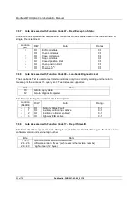
Manual Movement Travel sets the amount of valve travel not under motor action that is permitted
before being considered 'Manual Movement'. The setting must be sufficiently large to cover over run of
position control due to valve inertia. Too small a setting will result in Manual Movement alarms each
time the valve is positioned, particularly if the deadband is small.
8.1.10 Watchdog Timeout (Register 18)
If the watchdog trips to reset the processor the Watchdog Recovery data bit is set. The data bit will
automatically reset to '0' after the time period set in this parameter register.
8.1.11 ESD DI-4/Net Disable (Register 19)
In the IQ/IQT actuator this input determines the mode of operation for the ESD/DI-4 remote input. The
input can be used either to disable control of the actuator from the network, or to act as an ESD/digital
input. When this setting is made 'Active' the input will disable network control of the IQ/IQT when the
contact input is closed irrespective of the Aux Mask setting.
8.1.12 Analogue Input Max (Register 20)
The MFU includes an analogue input channel for a process input. This input will require calibration to
ensure it is accurately reported.
This parameter can only be set when the MFU is on line and the analogue input should be connected
to a calibration source. When the register is set this causes the analogue input to be sampled and the
value read to be used for the input to be reported as 100.0%. If the parameter register is simply read
then the value displayed is the raw analogue input value.
Apply a 100% input and write any number between 1 and 1023, but different from the currently
register value, write the new value and read back from the MFU. The number in the register will
change to the raw A/D value equivalent to the currently applied analogue signal and the reported
value for the Analogue Input in register 4 will read 1000 decimal, 03E8 hex (100.0%).
8.1.13 Communications Fault Timer (Register 21)
Parameter register 21, the Communications Fault Timer setting, determines the number of seconds
that network communication must be absent before the setting for the Fault Mode will be carried out.
8.2 Modbus Network Related Configurable Parameter Registers
These parameter registers set up the MFU for network communications.
8.2.1
Modbus Address (Register 22)
The Modbus Address is the address on the network that the Modbus Module will respond to. The
address can be in the range 1 to 247, though 247 is generally not used as this is the default address
and may be used by any newly introduced device on the network.

